simplified explanation:
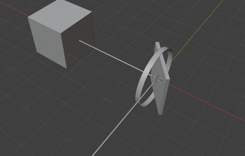
cube is the emitter, plane is the reflector (turret)
at perfect 45
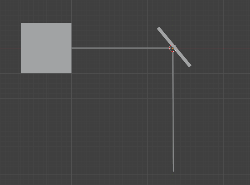
any more and the system can start burning its own body by reflecting the laser into itself
simplified explanation:
cube is the emitter, plane is the reflector (turret)
at perfect 45
any more and the system can start burning its own body by reflecting the laser into itself
it might look reflective but it almost definitely is not reflective in the IR spectrum on which the laser operates
way over exaggerated here, because at the range these engage it would be fractions of a degree incidence angle
so if it isnt reflective, how is it able to steer the Laser in the first place
i dont think you understand
the laser is reflected from the turrets into the incoming missile seeker
its the maximum limits of the CIRCM that can be calculated
the LAIRCM is another story but even that has limits
and? how is that the limit here
because the reflector would just need to have a limit of slightly over 45 degrees to cover that angle range
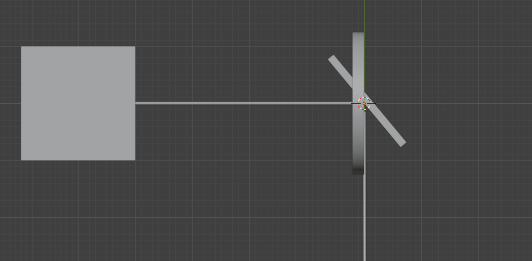
how would it start burning itself when the laser is still being reflected out through the dome, which we can tell it could be due to the pivot for the reflector being well past the edge of the dome
the pivot should be ~twice as far past the boundary than you depicted it as
and you are overestimating the strength of these lasers, they absolutly would no be able to significantly damage the metal part of the housing in their average engagement time of the system
Wouldn’t pushing the reflector a few cm up solve the problem right away?
it would, and as you can see by the images it is further out than he depicted
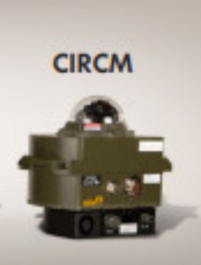
it would and it does on the LAIRCM by northrop grumman, but the CIRCM is an embedded design, hence why it is in this restriction
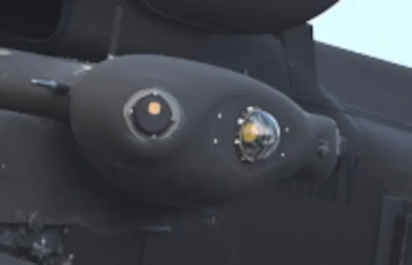
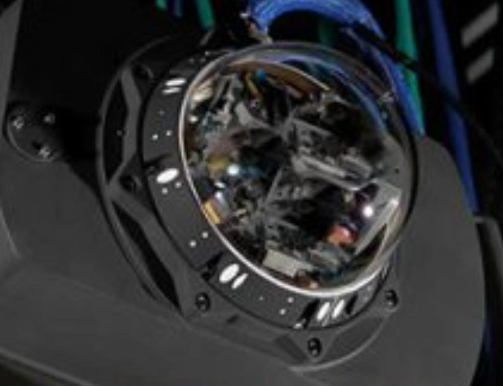
refer to this
CIRCM directors are embedded into the gimball assembly
a full 90 is not possible
also see here
Okay, I understand now why you said 90°. Originally thought the thing was a direct laser, not a reflective one. Then yeah, your reworked bubble seems accurate. I stand corrected. Nice discussion, thanks.
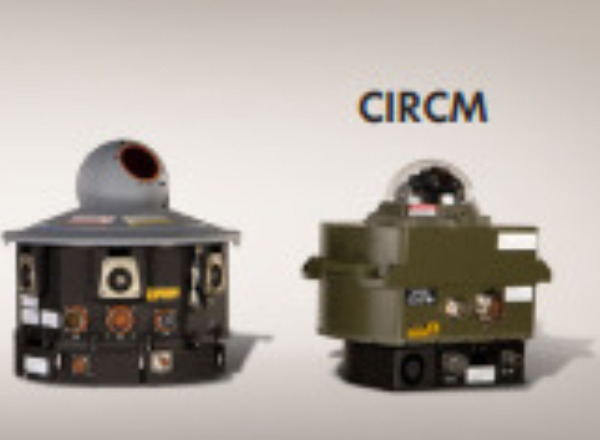
i thought so too, but then i read saw the official brochure displaying the tracker (turret) and Laser (emitter) seperately
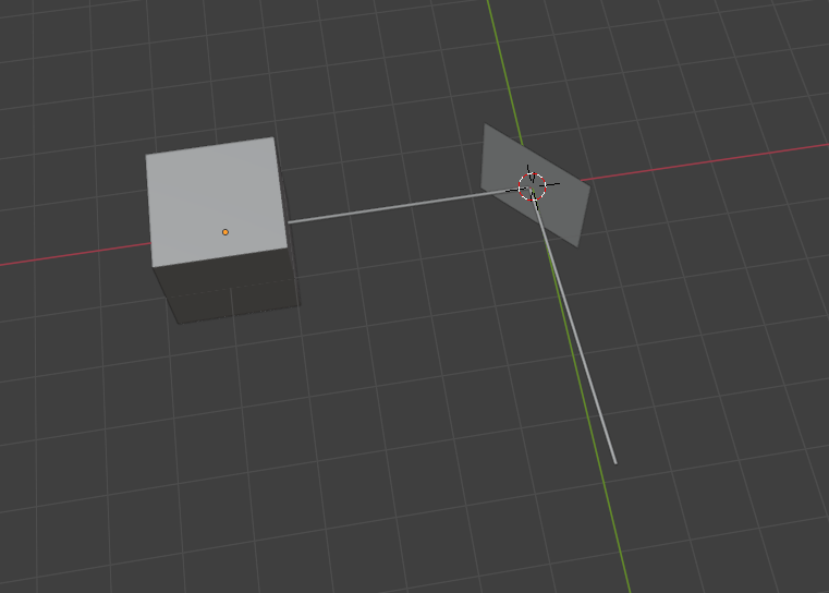
the point of reflection is most likely where the axises of rotation intersect as that would produce the most easily controllable system and minimizes the reflector size and therefor over all system size and complexity
in which case as you can see in this image the point of reflection is well outside of the housing, and would have be able to direct past 90 degrees
this is all assuming a simple flat reflector, where with a complex reflector design they could easily direct past 90 degrees

which is not at an equal ‘elevation’ as the outer opaque wall. it is below it.
‘complex’ reflectorswould just end up becoming a lens, convergent or divergent.
it is actually well above it
I have marked the position of the pivot and the edge of the housing, as you can see the pivot is well outside the edge of the housing
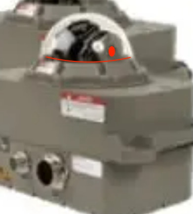
additionally as it pivots around the center of that point, and the beam width is likely roughly the size that I marked, there is clearly a capability of aiming past 90 degrees
Isn’t Snell’s Law worth consideration, it would potentially gain a few degrees of play if the dome’s distortion was mapped.
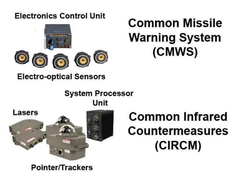
its worth pointing out that i seem to have seen 2 different types of pointers

however, the second one would be limited to 90 degrees merely because the base of the traverse gear does not allow for anything to depress below it.
i cant really understand the first one cuz its a mess
seems like an empty housing to test the traverse
So despite us testing it… you think it’s still over preforming… talk about propaganda warrior.
z-10 was by far the best
Someone flagged this as spam because they’re upset it’s true… really? Like really?