IIRC the folding fin version was a prototype for internal carriage. Photos always show the missile being carried with fins deployed:

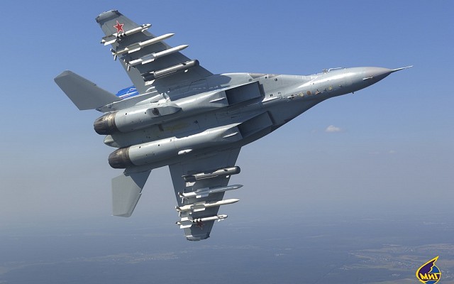
IIRC the folding fin version was a prototype for internal carriage. Photos always show the missile being carried with fins deployed:
The equation for drag is:
F_D = \frac{1}{2} C_D \rho v^2 A
As it scales with velocity squared (i.e. drag scales exponentially with speed) you would always expect an element of exponential speed loss regardless of drag coefficient. Obviously the way drag coefficient changes with speed for grid fins complicates the matter, but I very much doubt a simple logarithmic curve for velocity Vs time would be correct.
There’s a photo circulating the Warthunder discord servers. It seems that this may be what Gaijin used to model the R-77? I’m not exactly sure. I only have the picture, not the cover. It seems to claim that the R-77 has the same range as that of R-27R.

We know the R-27Rs range according to the MiG-29 manual.

I have been reading into the subject regarding the drag characteristics of grid fins for some time now, and I have made some findings; which I feel have been ignored a bit.
This honestly does make me question if the issue people have been discussing about is as prevalent as it has been made out to be. It has been discussed a lot that the issue lies in with excessive drag, but based on my findings on multiple sources; I have come to conclude that grid fins have a lot more drag in general than normal planar fins.
Multiple studies regarding the subject confirm the matter as being such. This particular study I am looking at right now, made by the Air Force Institute of Technology (https://scholar.afit.edu/cgi/viewcontent.cgi?article=4918&context=etd) regarding the subject matter puts it rather straight:


But the TLDR from what I’ve understood is that the drag in almost all condition is notably greater than in normal planar fins. Multiple studies seem to conclude that as being the case. An averaging out of all the various drag values comes to around 39% increase compared to planar fins. Which is what I have seen people propose Gaijin did with the fins.
The trade off for this extra drag is the extra maneuverability, and the other advantages grid fins provide (smaller motors required, and also the possibility of folding them which feels like it was a key thing with the missile…)

Legend:
M∞ = free-stream mach number
CA = axial force in missile axis
CN = normal force in missile axis frame
Cm = pitching moment in missile axis frame (with respect to c.g.)


The general consensus/summary from what I’ve gathered now is the following:
And as such, I honestly raise into question if the “incorrect” modeling of the grid fins would have that much effect to begin with? My findings personally seem to indicate that they do suffer a lot more drag than regular planar fins to begin with, which makes sense. Obviously, if it was modeled to always have the transonic drag, then it would be problematic. But the issue is that the fins suffer from more drag practically in every possible flight profile.
But what do you all think? Is this something we have overlooked?
iirc, grid fins only have improved drag characteristics over planar fins at “high supersonic” speeds, or at high AOA’s. This arguments been had over and over for some 2 years with many papers cited and compairisons made, but the grid fin crowd continues to refuse to believe that they arent the greatest thing to have ever happened to missiles.
Theres also the question of why gaijin would bother modelling a highly complex non-linear drag profile for fins that are only ever seen on 2 AAM’s (R-77/-1) instead of spending their time and ressources on other tasks.
End of the day, unless ppl have actual test data, or primary source data on what the R-77 should be able to acheive, every complaint about its range amounts to just being assumptions made based on peoples feelings that have been canonized by group conciousness. ie: if some ppl repeat something enough, others will begin to believe its true without actually questionning it.
Based on my own research, in the drag table section; even that is not true. The range disadvantage is prevelent at all mach speeds; but at mach 3.0 and above the disadvantage is minimal. (Around 0-10 percent increase in drag compared to planar fins…) Essentially, at these speeds, the drag becomes only on-par/equivalent to planar fins.
The advantage of the grid fin design doesn’t lie in the range, but in the maneuverability advantage it provides especially at higher mach numbers and ranges. Most of the papers I read seem to come to that conclusion regarding them. There is also the interesting side of swept/slanted grid fins which the NASA paper touches and focuses on quite a bit.
From the understanding I’ve reached, there’s a reason the grid fin design isn’t really used outside of Russia; because it has that disadvantage in range. However, a swept/slanted grid fin design seemingly does mitigate some of these issues. I think it’s around a 30% performance increase in general? The swept and slanted grid fin design in particular helps with the transonic issue.
Of course, this isn’t relevant to the R-77 as it doesn’t use slanted grid fins; but it’s still somewhat interesting nonetheless.
And honestly, yeah. That is the unfortunate truth. But as I outlined in my post – I think people have hyperfixated on this aspect a bit too much. From my current understanding, I think the performance increase in the missile’s performance would be minimal, even if it would be implemented. But do not quote me on that!
I need to do some testing myself to figure out just how the missile is modeled currently in-game. Because I still am not entirely sure just how Gaijin modeled it. The averaged out drag theory does seem to be the most prominent, but I can’t be sure yet.
But I think ultimately what speaks the most of this is the fact that Russia never really adopted the initial R-77 in the first place. Instead, operating the upgraded R-77-1 which we hopefully get soon in the game. But that missile obviously still suffers from the same issues as the R-77 due to it’s unswept/unslanted grid fin design. It’s no wonder in my opinion that Russia is trying to phase the R-77-1 out in favor of the R-77M which has traditional planar fins, because the range/drag performance in grid fins is just that much worse. As said, the advantage lies in maneuverability; but we all know that in modern air combat range is what matters most.
Ultimately, I have to do some testing myself before I can come to a definite conclusion regarding the subject myself. But I do not think my hypothesis/understanding regarding how grid fins really do hamper range quite drastically is unfounded, as practically every source I’ve read on the subject seems to support this claim.
The only ultimate performance test I can think of is the bomber headon on high altitude:
Rosoboronexport tells us the max launch range the RVV-AE has against bombers is 80Km, which is the same in this chart.
That chart states a max launch range of 100km, not 80km. Also iirc that chart isnt official at all.
Also of note, the highest launch conditions you might see in-game are in the ballpark of 10km alt, likely against targets below you as well. The engagement envelope according to that chart for such altitudes in head-on shots is like, 40km.
All of these studies baselessly assume the grid fins on the R-77 are quite thick compared to the real life dimensional data and use wrong taper ratios etc.
The data for the R-77 in there is incorrect as mentioned above comparisons for generic grid fin are valid but cannot be assumed that the R-77 matches the data. They could have also used a planar fin that was more indicative of what we see on real air to air missiles instead of the one they used.

Even this 2020 thesis study is incorrect;

Rosoboronexport states 80Km
I know, what Im saying is the chart doesnt match rosoboronexport numbers, it exceeds them by 25%, and that even if the chart was accurate, which is a massive if, the launch ranges according to it in-game would be at most in the ballpark of 40km.
The chart is made up and is from the Indian defense forum or similar, the rosoboronexport numbers are no more useful than airforce and navy sites that say AIM-120 has 20 miles range.
Well then, I guess the only other way of proving something is analysing the in-game R-77.
One thing is guessing Gaijin used a constant average drag value for the R-77, other is actually proving it.
@Busheedoh said that the fourth bug report got stonewalled because it quoted a datamined value.
But then it is as he said too:
I don’t see how that’s relevant though? The underlying issue with grid fins still persists even if the taper ratio or thickness of the R-77’s grid fins are different. The performance change you speak of would be minimal at best. As I outlined in my reply post The R-77 'ADDER' - History, Design, Performance & Discussion - #716 by Busheedoh; the NASA study points out that the right thing to do in an aerodynamics is to slant them.
This would actually have a very noticeable performance difference, especially in the transonic region, but as we know, the R-77’s grid fins are not slanted.
My table may not represent full picture, but I don’t think the values I present are too far from the truth even in the case of the R-77. What you say doesn’t invalidate these studies as a source of information regarding the subject of drag regarding grid fins.
Taper ratio?

I have an ideia on how to discover this, if you want to test it.
Could you elaborate? You can minimize their transonic drag through thinner grids with sharper points, all of the studies have absurdly dull or thick grids.
This would drastically increase production costs for ultra thin grids designed for a medium range air to air missile I’d think. Even so, the ratios and thickness of the grids used in these studies are quite absurd.
@BBCRF is working on a proper CFD model of an R-77 based on better data. From this we can compare to analysis of AIM-120 or any other air to air missile under the same circumstances and develop an unbiased picture of what the drag and lift coefficients are between the two.
I did some new calculations.
This time I separated the change in speed on each second and then removed the speed contribuition to the drag acceleration.
What is left is the orange line, which would be constant(I expect so) if altitude also wasn’t a factor in this. It does suffer a variation from the time parameter, but it doesn’t have the same shape as the other two fucntions, the speed and the acceleration in each point.


Drag can only at best be mitigated. The point I was trying to drive in with my post is that the universal drag is much greater than that of planar fins at all air speeds. The reason for this lies in their namesake: the gridded design.
The multi-plane construction increases the total surface area exposed to the airflow, causing more resistance and turbulence. This results in overall much greater drag, compared to planar fins. The increased overall drag gives the fins grants the fins their unique ability to have more immediate and finer control over the air passing through them.
This, is the key strength and weakness of grid fins. It’s what makes them unique, but it’s also their biggest downfall in this context. Their range is severely hampered by that drag, as it is traded for maneuverability. Which makes them good for shorter range munitions, due to their high AoA capability, but renders them rather lacking for implementation as long range weapons.
There are of course the other advantages of grid fins such as the smaller hinges that are required for their movement, their compact size and everything else that is discussed. But I want to now back up my words with an additional source, that you can go review and read for yourself.
This 1998 research paper from the High Speed and Weapon Aerodynamics Department of the UK goes into detail of the effects of grid fin design on airflow, especially in regards to drag. Which is what we are talking of in this case.
Legend:
“During the experimental phase of this research two designs of lattice control were mounted on an existing missile research model and tested in both the DERA (Defence Evaluation and Research Agency) 8ft x 8ft wind tunnel, at Mach numbers from 0.7 to 2.4, and the 3ft x 4ft facility at Mach numbers from 2.5 to 4.5. Conventional controls had been investigated previously at DERA Bedford, using the same body, and the current investigation capitalized on the availability of the conventional data, covering an identical range of Mach numbers.”
The following were the control surfaces utilized in testing.
Along with this, here are the bodies used in testing.
“Overall forces and moment were measured using a six component strain gauge balance, hereafter referred to as the main balance. Individual tin forces and moments were measured on two of the four fins using four component panel balances.”
You can go review the rest of the document yourself, but I wanted to outline the conditions the tests were conducted in before going into the meat of the subject. The core findings of the document confirm what many other studies on the subject have confirmed, that being a increased level of drag at almost all air speeds.
It is clear as day that the gridded fins (L1 and L2) exhibit much greater drag than the planar fins (C1 and C2) across the board. The paper says this regarding Figure 23, in the next paragraph of drag characteristics.
“The variation of incremental axial force coefficient (∆Cx) with Mach number at zero incidence is shown in figure 23. The data shown includes the total axial force on all four fins. At both subsonic and supersonic speeds the lattice controls exhibit much greater drag than the conventional controls. At Mach 4.5, for example, L2 has an axial force 3 times greater than C2. In the supersonic regime lattice axial force coefficient is almost constant with Mach number in contrast with the significant drop off for the conventional controls. The fact that L1 exhibits greater drag than L2 even though they have similar lifting capability confirms that it is possible to tailor drag by varying the lattice geometry without reducing control effectiveness. The difference in drag is due to the extra wave drag generated by the larger cross-sectional area of L1. The variation of axial force with incidence is moderate for the lattice controls and for most mach numbers is not significantly different from the conventional controls².”
There were of course additional tests conducted for stability, different AoA angles and etc – but I do not want to copypaste the entire document here. You can go read it below.
The paper concludes with the following core takeaways regarding the advantages and disadvantages of gridded fins over planar ones.
“Lattice controls offer the following advantages; improved yaw stability at incidences up to 24° (due to the ability of the lattice controls to generate side force), small hinge moments with minimal variation of centre of pressure with Mach number and incidence, and the attenuated effect of body vortex interference, improving roll control and autopilot demands. The available data also indicate that lattice controls may offer improved yaw stability at high incidence, which may increase the LATAX capability through increased controllability at these incidences.”
“Lattice controls suffer the following disadvantages; large axial force, which can be as high as 3 or 4 times that of a conventional tin, poorer control effectiveness for a given static stability than a conventional square planar fin, and a decrease in lattice control effectiveness in the transonic region (due to the individual cells choking). However, lattice axial force can be tailored by correct shaping of the frame and web cross-sections, and by careful design of the lattice geometry. In the transonic region lattice control axial force may not be significantly higher than that of conventional tins.”
Source: $MP-005-09 simpson | PDF | Flight Control Surfaces | Fluid Dynamics
In essence this paper confirms many of the things I discussed earlier in my post regarding gridded fins in general. It also outlines that the drag exhibited by grid fins (that were tested) can be as great as 3 to 4 times greater than that of planar fins. Which many other papers back up, including the ones I linked before.
As I said above, this comes from the gridded design and how the multi-plane construction of the lattices/grids just covers more surface area than a planar fin. It’s common sense that a surface like this would exhibit greater overall drag than a planar one – which simply cuts through the air. It is my opinion, and that of many other papers, that grid fins can never really be on-par with planar fins in terms of aerodynamic drag. Because their purpose is exactly to have more drag so they can exercise more control over the airflow, thus making them more maneuverable.
To repeat myself and make myself clear: what I am trying to communicate is the universal increase in drag that is a result of the grid/lattice fin design. An increase in drag is not only found in transonic condtions, but in all flight conditions. The R-77 is not exempt from this… And we need to take that into account when looking at this topic, instead of exclusively focusing in on the transonic drag.
But now, I want to cover the measures that can be taken to mitigate the drag.
I will cover theses topics one by one. Starting off with the thickness of the lattice, and how that effects it’s performance.
As I outline above in my post, higher drag (when compared to planar fins) is something that’s practically a intended feature of the lattice/grid fin design. It is something that can only be mitigated, and will always be something that “plagues” this sort of design.
The effect of actually making the material used in the lattice thinner is something I have read a bit more into now. But my general understanding is that it comes with it’s own costs. Especially if we chase a “ultra thin grid” as you outline.
One of the core issues with it is the thermal and physical strain/stress that such a thin surface would be exposed to, especially in regards to a missile. Degradation of the material used in the lattices in these conditions is practically guarenteed, and becomes a real issue the less thick the material is. Another issue is optimizing the airfoil of such a thin material. Along with this, the production cost of making such a thin material that functions as a optimized airfoil is another whole issue.
The effects of the thickness on the drag were actually outlined in the document, the one you discredited in your reply to @MythicPi – practically right below figures 6, 8 and 8. So we will now return to the AFIT paper, and cover the effects of thickness on the drag caused by lattice fins – so there is no confusion regarding the subject.
Legend:
The different lattices utilized in additional testing:
“The next sets of tests that were taken at the ARF involved different lattice grid fin
geometries. They first used the baseline fin model used in previous tests. Next, they had
a ‘thin’ fin model which had a web thickness at 0.004d compared to 0.007d for the
baseline model. Finally, a ‘coarse’ fin model was produced with an elimination of some
of the webbing. Figure 14 shows the comparison among the three types of lattice grid
fins tested.”
We can see that they tested multiple types of lattices. And in the section below they lay out a graph detailing how each one performed.
“When calculating the results, the reference length is from the model diameter (d)
and the reference area is the cross section area of the model (A= π/4*d 2 ). The zero yaw
drag coefficient (CXo ) versus Mach number flight data can be seen for all the
aerodynamic coefficients and derivatives in Figure 15. The drag data indicates a
reduction in drag of 16% for the ‘thin’ fin lattice grid and a 22% reduction for the
‘coarse’ fin lattice grid. The authors believed this to be true because drag is ‘directly
related to the thickness of the webs and the number of webs present.” (16)”
As is evident, even the thinner lattice only has a drag reduction of 16% compared to the baseline one. Which while still a reduction, it isn’t anything major. They also tested the transonic drag, and especially flow choking.
“Figure 16 contains the pitching coefficient derivative (Cmα) ARF data as a
function of Mach number. As seen before, there is a discontinuity at a certain transonic
Mach number. But, this time it occurred near Mach 0.8, not 0.77 as before with the
baseline model.
From these experiments, the authors concluded that choking occurs in the lattice
grid fins at a critical transonic Mach number for any of the grid fin configurations. This
choking causes some temporary instability of the missile flight dynamics, even though
the Mach range of this instability seems to be quite small.”
The paper then goes into detail regarding flow choking. But the general takeaway is that the effect of the thickness of the lattice is not as large as you might expect. Which is why this shouldn’t be discredited as a source regarding the matter – as it still serves as a good insight into how drag effects grid/lattice fins.
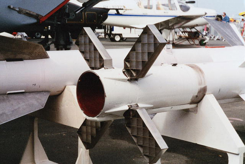
Now. I will admit, that I am not entirely sure of the dimensions of the lattice fins on the R-77. As I have been reading mostly into the general performance of lattice based fins. I’ve put some close up photos of the fins above, and at least at a glance – the ones used in the comparing of lattice thickness in the AFIT study do seem to match. If you could, please give precise measurements of the fins here. Thanks.
But, finally, I want to discuss and go into detail regarding the effect of the leading edge in lattice fins. Which seem to actually have the most effect to drag, and that makes sense – because you are optimizing the air flow. But it should still be noted that the drag exhibited by the fins will practically always persist.
This paper gathered by Mark S. Miller and Wm. David Washington goes into detail on the subject. So let’s digest the core take-aways from there.
Note: I apologize for the poor quality on the images of this document. I hope it isn’t too hard to read.
Figure 1
“An experimental wind tunnel test program was developed and implemented in order to investigate two different techniques for reducing grid fin drag levels. A total of six variations of the baseline grid fin design shown in Figure 1 were tested for Mach numbers ranging from 0.5 to 2.5. The principle objective of the test was to evaluate the effects of outer frame cross-section shape and web thickness on grid fin drag levels. This paper first provides a brief summary of the wind tunnel test program. Test results are then presented that show the effects of these design parameters on grid fin aerodynamic characteristics.”
The initial configuration/reference point was the F1, which had an internal web thickness of 0.008 inches (0.203 mm) with no leading edge. See Figure 1 for further info.
The F1 configuration was modified with different sorts of leading edge configurations. So the thickness of 0.008 inches (0.203 mm) was kept. These go as the following:
Another thing that was tested was fin balance. The practical effect of which can be seen below.
Notice how the fin is facing the other way in balance №4, when compared to №2.
The paper then covers further testing configurations in detail. The things that were tested: Normal Force, Hinge and Root Bending Moments but what we are here for is drag, or axial force – so we will focus on that.
Figure 7
“Figure 7 presents axial force coefficient (CA) data versus angle of attack for Mach numbers of 0.7, 1.2, 1.8 and 2.5. The first and most obvious conclusion drawn from the data is that the level of grid fin axial force can be varied considerably by altering the frame cross section, the web thickness or
a combination thereof. Two additional observations are that grid fin CA values are essentially constant for small angles of attack and that differences in configuration CA levels remain consistent with variations in angle of attack.”“CA levels remain consistent with variations in angle of attack. The baseline grid fin configuration with no frame shaping (F1) and the thick web configuration (F5) generate the highest CA levels for all Mach numbers tested. There are small differences between the modified single wedge (F3), half-diamond (F4), and thin frame (F6) configurations. subsonic data show a significant increase in CA values at higher angles of attack. The transonic and supersonic CA data show a moderate reduction in CA at higher angles of approaching a 30% reduction at – attack Mach 2.5.”
The paper also covers drag coefficient in-depth, if you wish to see that. The following tables summarize the effects of different leading edge configurations on drag.
The study concludes with the following core takeaways for our purposes:
Frame shape and web thickness significantly affect drag.
Optimizing the leading edge configuration can reduce drag across all tested Mach numbers.
Thinner lattice structures also lower drag but structural integrity must be maintained. (Refer to table for summary)
Effects of shape and thickness remain consistent across flight conditions.
Changes in angle of attack and Mach number do not drastically alter how leading edge shape and lattice thickness influence drag.
Drag increases predictably with lift coefficient (CL2).
At moderate angles of attack, grid fin drag follows a linear relationship with CL2, similar to conventional planar fins.
With this, we have now covered the effects of optimization of lattice fins, in-depth. You are free to research the sources further yourself. So is everyone else. So, I believe still that my proposed drag table for grid fins; that I made in my original OP is still relatively accurate even in context of the R-77. Even taking into account the different optimizations. However, I could very much be wrong.
Which is why we should go forth with this either way.
But I would also like to note that the sources I have utilized should not be discredited, just because they may not match the dimensions of the R-77 to the teeth. I feel that in this post I have established, quite well that the drag that lattice based fins suffer is much greater than that of planar fins – across the board. In most if not all air speed scenarios.
Yes, it can be optimized – and a combination of all of these optimization techniques can most likely reduce to a noticeable degree, but as the 1998 UK study lays out (which has been used as a reference in multiple other research papers) the drag lattice fins exhibit is up to 3 to 4 times as great as of that faced by planar fins. But my belief is basically that it’s still “not enough” to make it comparable to planar fins.
It’s an uphill battle. The 1998 UK study references the 1993 USA paper, like so regarding mitigating drag:
“However, Miller and Washington have shown that by suitable adjustment of web thickness and frame cross-section shape the drag can be tailored considerably with minimal impact on other aerodynamic properties.” (Paragraph 1 of section 8)
“However, lattice axial force can be tailored by correct shaping of the frame and web cross-sections, and by careful design of the lattice geometry. In the transonic region lattice control axial force may not be significantly higher than that of conventional tins.” (Paragraph 4 of section 9)
So to conclude, I believe that universal drag that exceeds that of planar fins is present in almost all flight profiles of the lattice based control surfaces. How much does this exactly effect the R-77? I am not entirely sure. The design of the fins based on the photos I posted earlier does not incorporate any special measures to counter drag outside of presumably having a leading edge, and being relatively thin.
A NATO study from 2006 outlines effective ways to counteract drag presented by having localized slanted surfaces, almost sawtooth-like implements in the lattices. And repeats the general theme that the lattice surfaces exhibit excessive drag, when compared to planar fins. Which is a claim that most studies that I have read in the past few days from an array of sources have claimed to be the case.
The issue with the R-77 lies in the fact that it’s designers chose the grid fin design. And it is thus my belief that, even if the flight model of the missile in-game would be made as accurate as possible; it would most likely still struggle at ranged engagements. The design simply prevents it from being a proper equivalent to the AIM-120 AMRAAM.
Do I want the missile to be improved? Yes. But it has to be done in the bounds of realism. I look forward to the addition of the R-77-1 and the various improvements it will bring. But in the context of the conversation of the drag of the fins? We should focus on all the aspects, not just the transonic drag which seems to have been a vocal focus of this community. The R-77 suffers from greater drag than planar equivalents in all flight profiles.
That is my final conclusion that I have come to. Experimentation and further research will have to be completed to truly conclude the extent of the drag on the R-77. But we should shift our focus away from the transonic drag, to focus on the bigger picture of the effect of the grid fins as a whole.
What is your idea?
Interesting. Altitude influences drag a lot more than could be expected tbh.


