Not substantially, it does, however, have a much larger wing area.
4 Likes
I believe it is still under technical validation, but installation has also been confirmed on aircraft other than the ATDW.
https://x.com/himazin_180sx/status/1948715296069390526/photo/2

5 Likes
Yes that is what I am saying. We knew it should be technically compatible, but that testing was still being carried out, despite the AMC OFP rewrite which added it being over a decade old. This shows why its still undergoing technical validation, when the originally allotted validation period was something like 9 months
6 Likes
The report has not been updated, however, new data on this subject has been passed.
The inlet used on the F-2A is indeed MCID; it’s the MCID -713, which is different from the NSI. My apologies for preliminary data being incorrect. However, it has been corrected. This is also why your source notes it uses the MCID lip. It indeed uses the MCID lip; it uses the lip of the MCID-713.
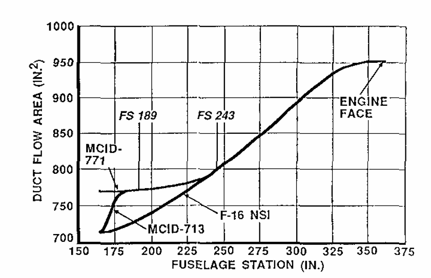
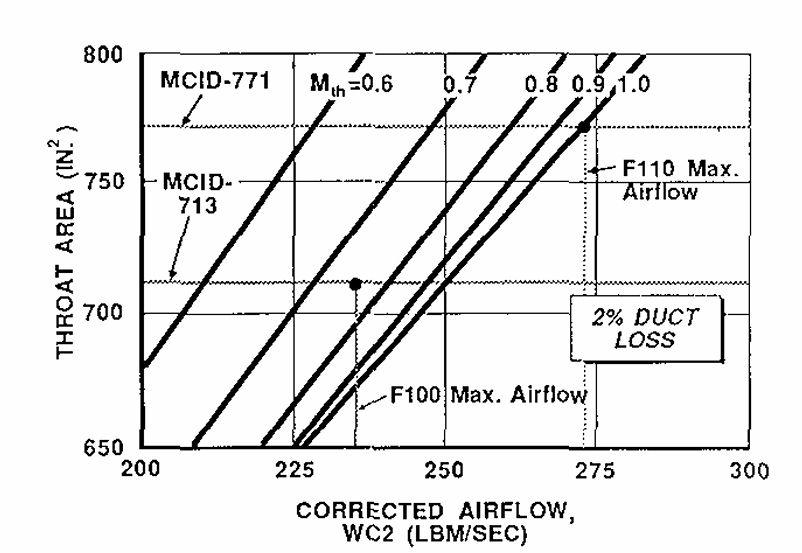
The MCID-713 inlet uses small-mouth capture geometry like the NSI while having the expanded duct of the MCID-771 (F-16C Block 50 large-mouth inlet). Notably it also has a slightly higher throat Mach number of 0.75. However, maximum inlet airflow remains similar to the NSI, and this is a big limiting factor when paired with the F110-IHI-129 engine. Please note that maximum airflow ties directly to throat area and capture geometry.
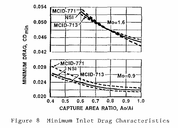
Compared to the MCID-771, the MCID-713 offers more stable performance at lower speeds (where the MCID-771 deteriorates) and considerably lower (3% - 4%) drag than the MCID-771.
Upon further investigation, pressure recovery and distortion has been found to be very similar for both inlets at relevant speeds so any possible transonic losses can be discarded without further data. However, the MCID-713 inlet of the F-2A undeniably has slightly superior characteristics to the MCID-771 at lower speeds when air mass flow differences are ignored.
7 Likes
This is not correct. The throat Mach number of the NSI/MCID-713 is more optimised for low speed and static conditions than the MCID-771. It’s essentially the other way around.
3 Likes
Thank you for your research, its much appreciated.
3 Likes
so would this be a buff or a nerf? From what I’m getting it would be worse at high speed making it even slower than it already is…
±, maximum inlet airflow is undeniably not optimal. However, drag is reduced by a pretty good margin, and losses lessen the closer you get to static thrust. It’s essentially a trade-off. I believe if applied on-top of the F110-GE-129 curve changes, assuming those are also applied to the F-2A, it should still be better than the current aircraft at certain speeds (?) and not as draggy. It’s down to developer implementation and how the data is interpreted, but that’s my take on it. Losses can be rounded down over the standard MCID-713 by optimistically calculating with minor geometry refinements unique to the F-2 in mind as well.
3 Likes
From my reading of it it’ll nerf it towards the very low end speeds where intake mass really matter, but assides from that a slight bump up (relative to the buffed Ge-129 curve from the F-16C buff)? Figuring out the fuel flow rate of the engine should be able to give us figures on when the reduced flow mass truly matters. I wonder if gaijin will actually reduce the drag from it though
Also, something, when I was looking for stuff to disprove it being NSI, i did a bunch of image comparison, and all of it has the inlet being slightly taller then NSI? So it is possible even the flow mass isn’t that different.


2 Likes
The capture geometry on the MCID-713 is ever so slightly different with a mild reverse duct slope. However, the major changes over the NSI are made in the duct where it retains the duct geometry of the MCID-771 and identical lip dimensions are retained otherwise. I do agree that figuring out the fuel flow rate of the engine is important to get a more refined idea of where losses should occur and how much. For the time being a definitive and mapped out lessened drag penalty over the F-16C in regards to the inlet is a nice to have.
2 Likes
The only thing i can find on it’s specific fuel consumption in AB is cm,A = 0.186 kg/Nh, as stated here, but that seems a bit high doesn’t it? Am i doing some math wrong or wouldn’t that be consuming well over 60 kilograms of fuel per second
2 Likes
Multiply by thrust in newtons and divide by 3600. Kilograms of fuel per Newton of thrust per hour. Keep in mind SFC varies with Mach and altitude also. Not sure how this figure compares to in-game.
i.e.
0.186x129,000/3600 ≈ 6.67 kg/s
1 Like
Yeah thats what i did, guess i misplaced a zero somewhere.
In game it maxes out a bit below 600 kg/min @ around 147,000 newtons
1 Like
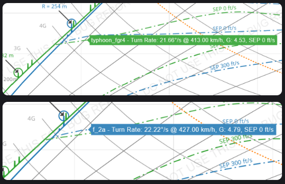
![]()
6 Likes
Weve peaked again
We now have a better low speed turn rate (marginally) than the Eurofighter
4 Likes
why are you using light mode?

1 Like
get flash banged
1 Like
Can you show b4 and after pic for the turn rate graph?
Low key light mode better for everything. I switched discord, insta, x and everything to light mode now