The New detailed interior for the M1A1 is wrong in several regards. several pages in the maintenance and trouble shoot manual proves this. (links to all is provided at the end) there is already a issue reported, please go support it: Community Bug Reporting System .
edit: the issue above is closed, new issues will be linked here.
issues reported:
wrong electronic power system: Community Bug Reporting System
wrong APU: Community Bug Reporting System
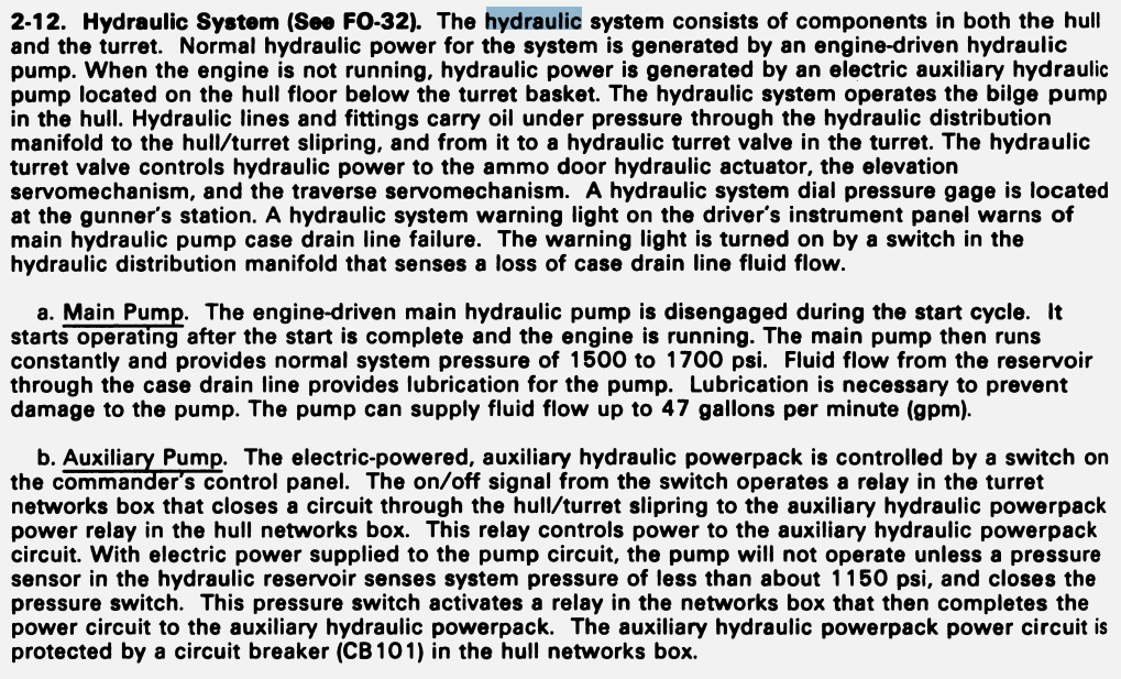
wrong hydraulic pump model: Community Bug Reporting System
wrong shape of engine compartment: Community Bug Reporting System
wrong FCS: Community Bug Reporting System
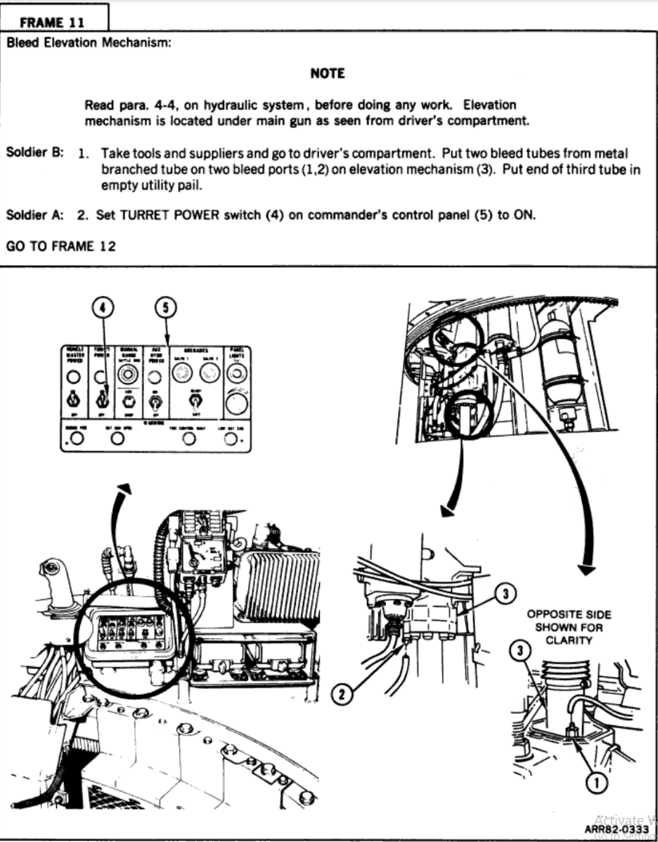
wrong elevation drive: Community Bug Reporting System
wrong traverse servo: Community Bug Reporting System
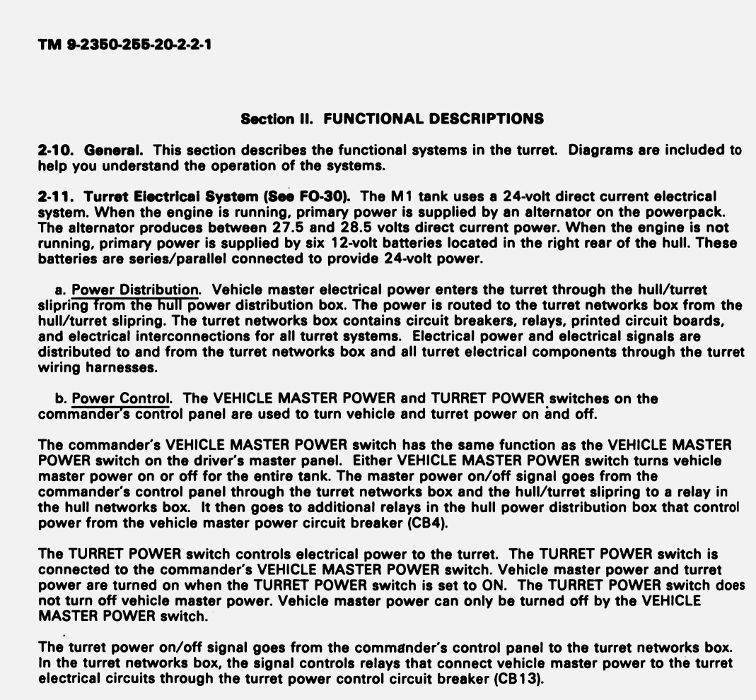
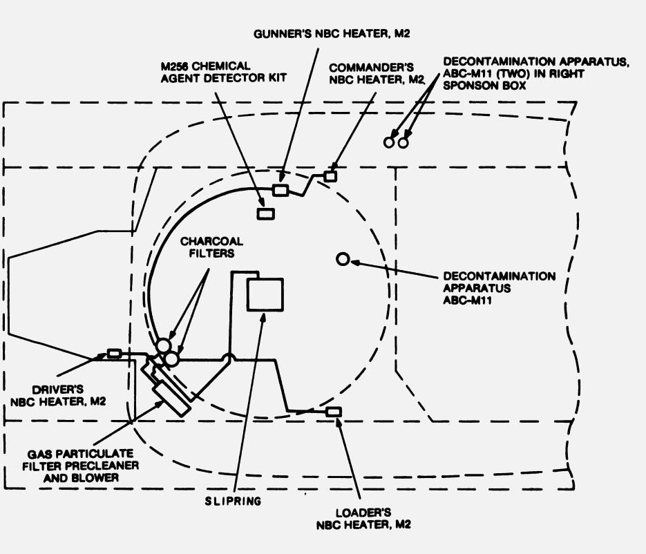
First the new battery Pack in the right rear of the hull is not the normal battery, it is the backup battery when the engine is off. the normal power is supplied by a alternator in the power pack. therefor it makes no since that it’s destruction would lead to the vehicle loosing power.
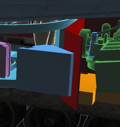
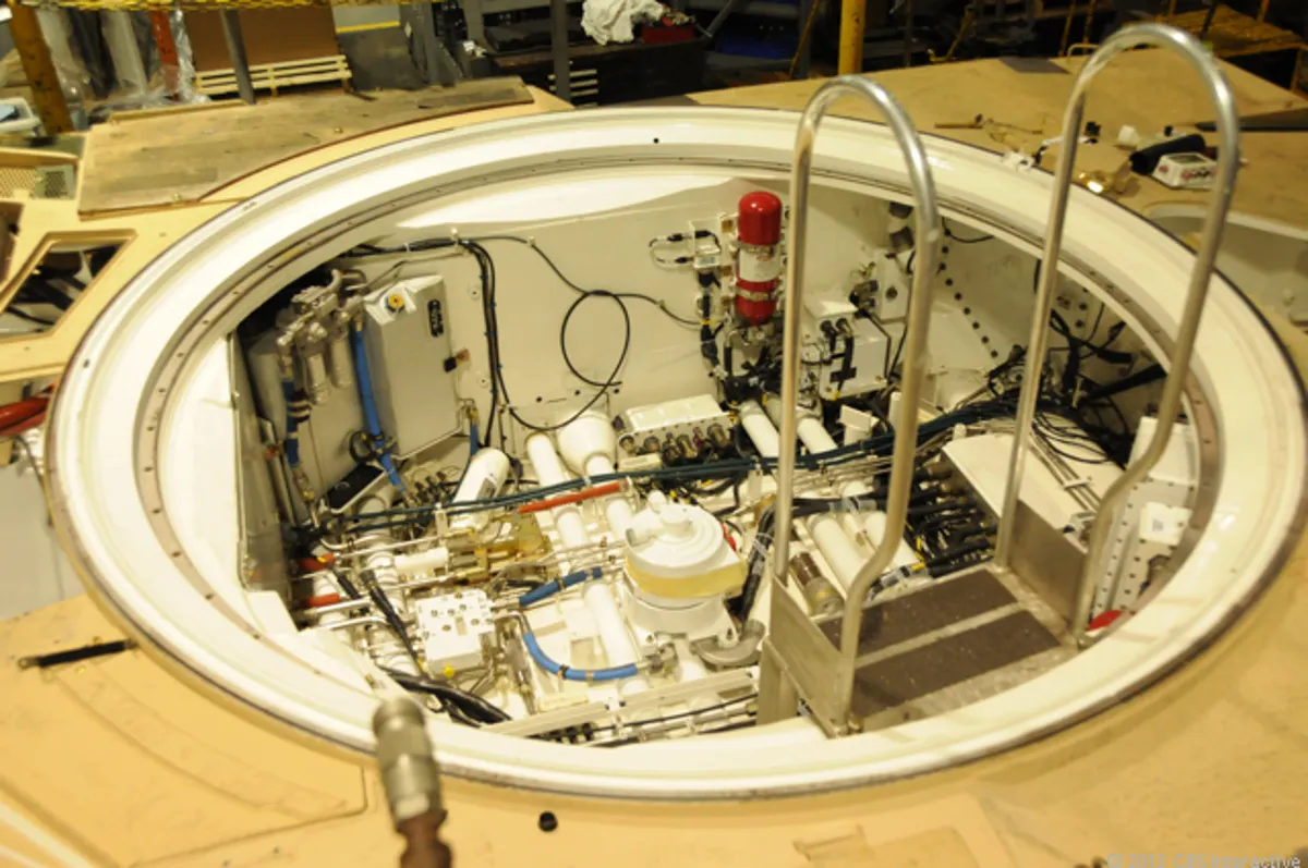
on the same page, the in game “APU” in the middle of the basket is the slipring (a system that allows piping to enter the turret from the hull).
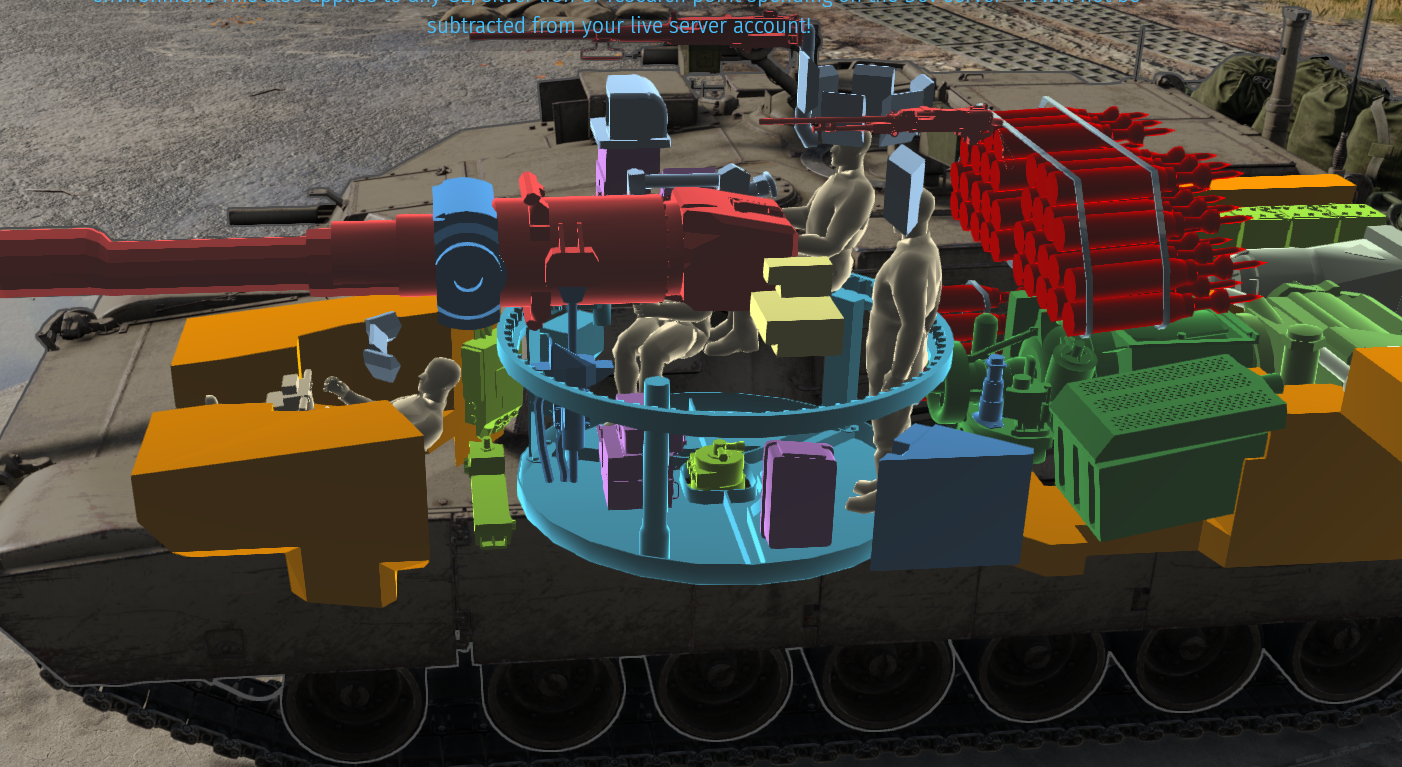
Second, the giant hydraulic pump in the left rear of the hull is also not present on the real tank.
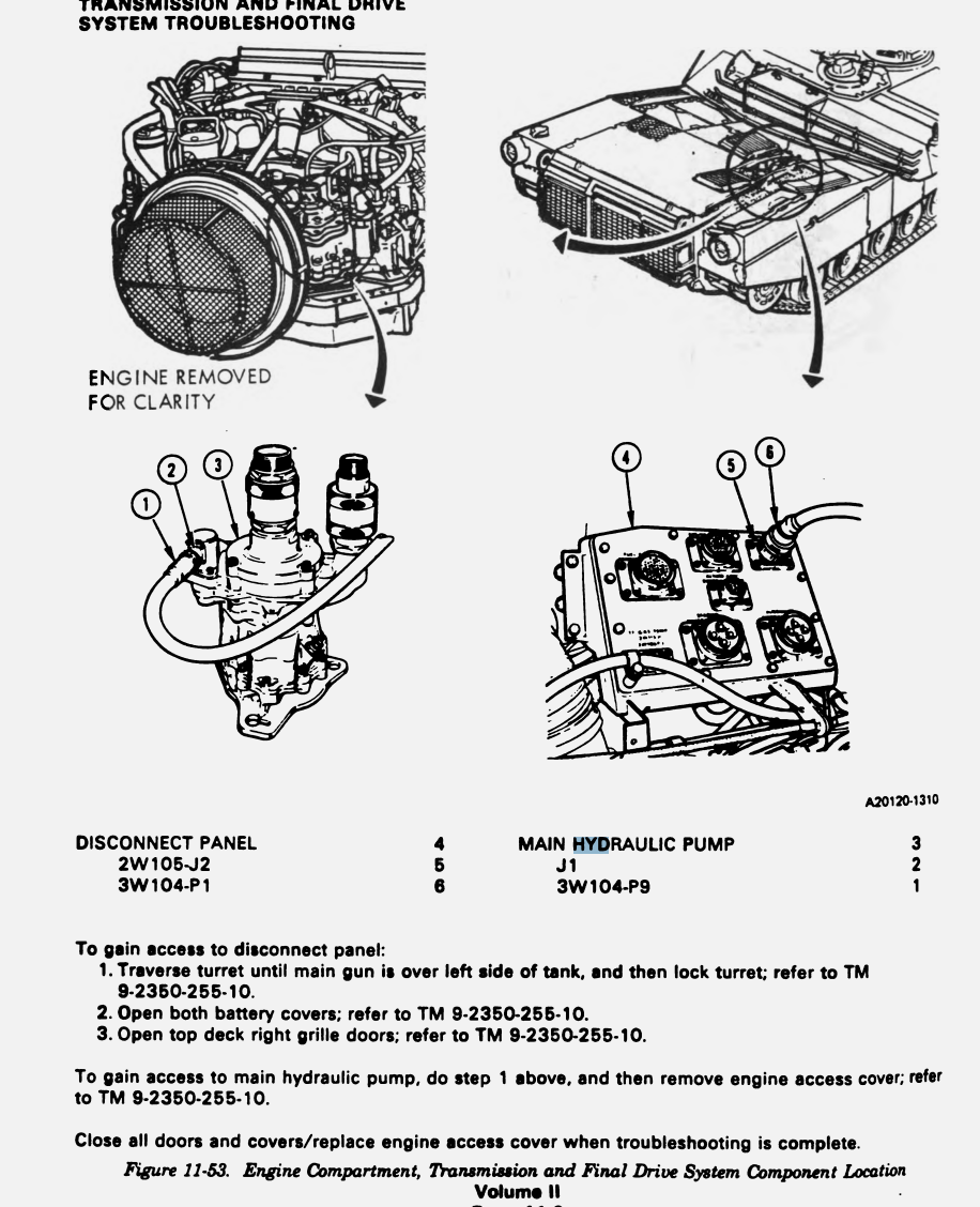
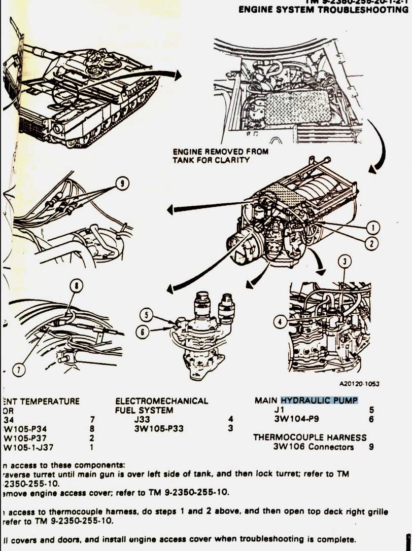
in the preceding two diagrams the main hydraulic pump is pointed to be in the power pack, right on the engine. Also on the two proceeding two diagrams, it is visible that the engine doesn’t have the protruding green box on the left side. The Abrams also have two hydraulic pumps one in the power pack and one on the hull floor below the turret, only one need to work for the system hydraulics.
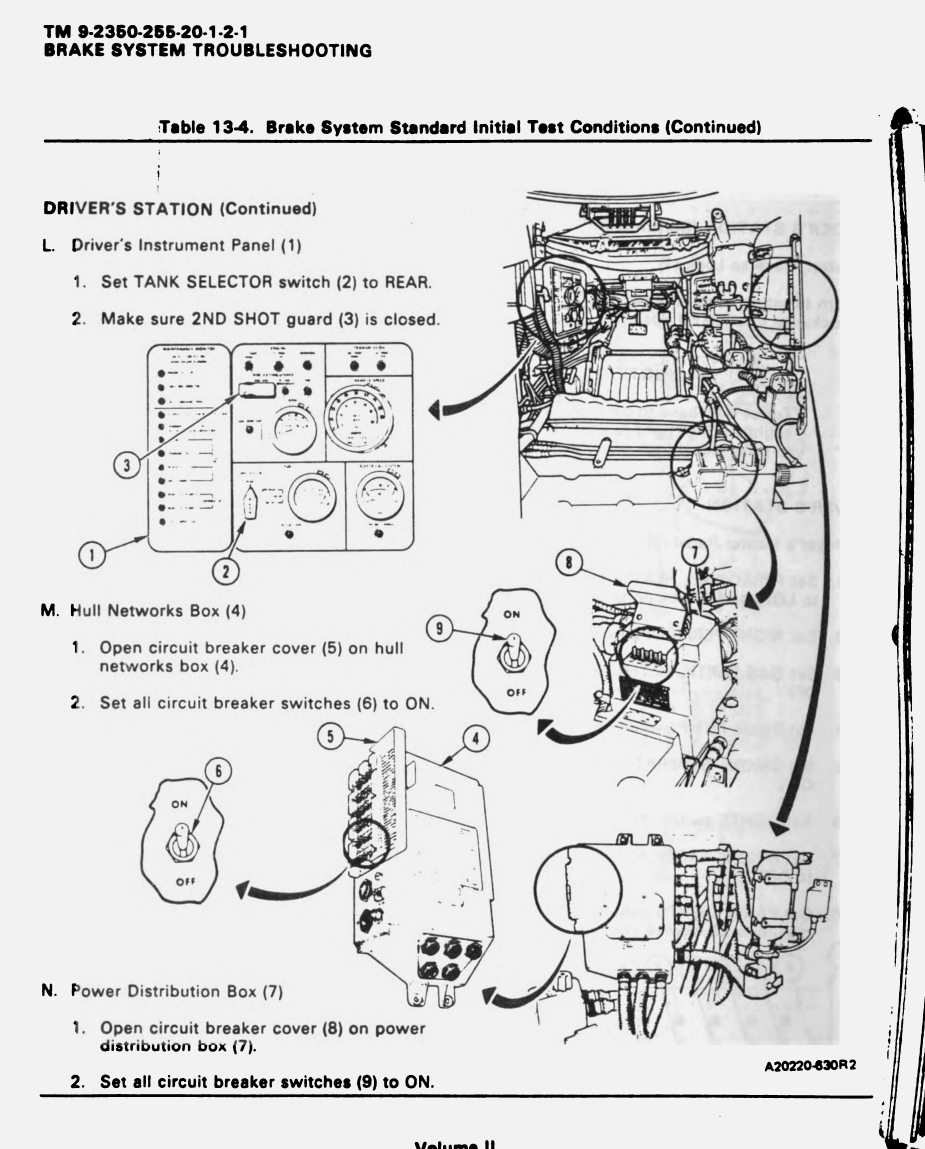
Third, the batteries at the front of the hull shouldn’t be modelled. The flatter bit is the power disruption box, and not a battery (no other MBT have is modelled by the way, the Russian MBT don’t even have batteries).
the taller bit is the hull network box, also not a battery, it controls data of systems and electronics in the hull of the tank, not the turret. (the turret have its own network box)
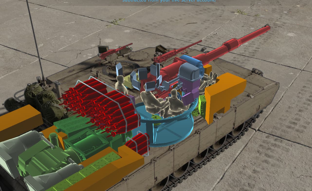
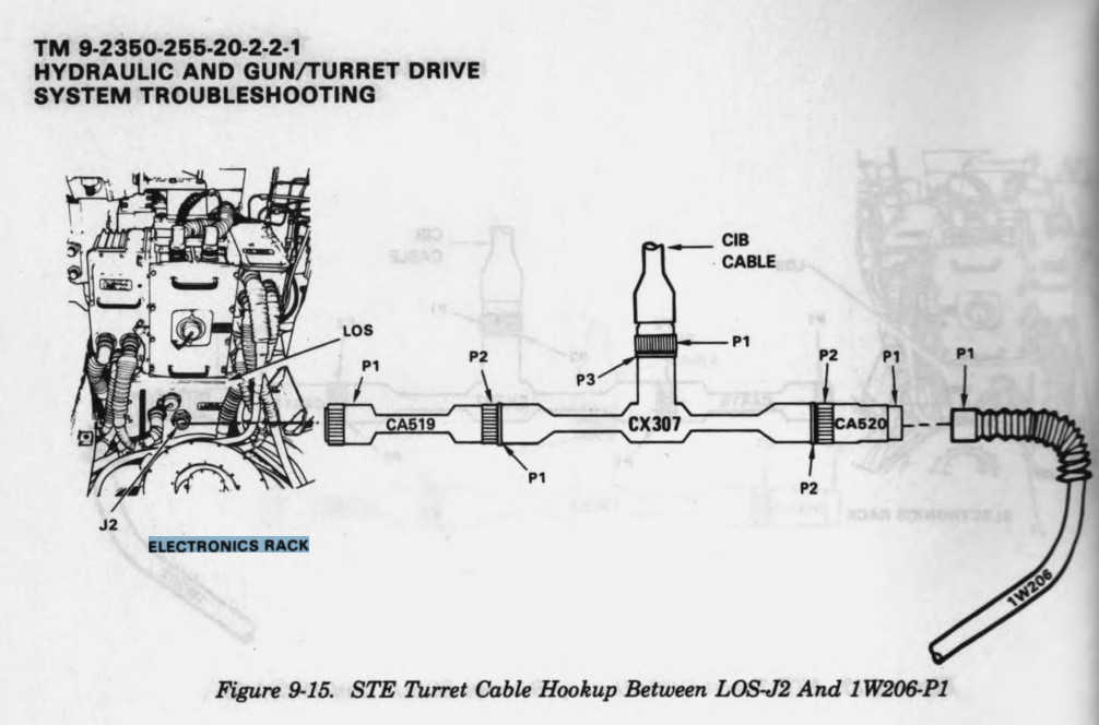
On the topic of which, the FCS modules should also be reduced in size to just the bit around the Gunner and the TC. The box on the loader side of the turret is TNB (turret network box). This controls data of systems in the turret, and is not a part of the FCS. Same with the box in the centre front of the basket, its a electronics rack and same as above, not a part of the FCS.

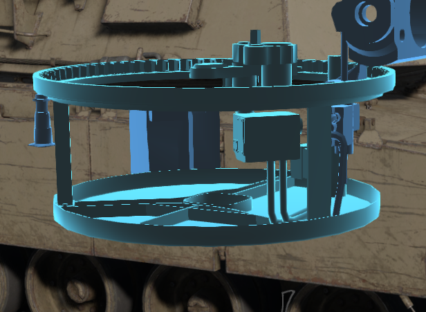
fourth, the elevation drive is wrong. while there is a elevation servo in the in game location, the actual drive is located above it as demonstrated below. Therefor, I don’t think it fair to have both the elevation dive and the servo mechanism count as the elevation drive.
Lastly, the blue box below the turret ring is the traverse servo mechanism. As the actual traverse drive is already modelled above it, I don’t think its fair to model the servo for the same system. also the bottom of the basket and the post at the rear left of the basket should have not should have no hit box, as they are both just inert metal on the real tank. it is also debatable if the post at the front left of the turret should have a hit box as it is just a hydraulic accumulator on the real tank.


sources:
M1 matnance guide: Tank, Combat, Full Tracked, 105-mm Gun, M1 (2350-01-061-2445) General Abrams Turret, Organizational Maintenance Manual - Google Play Books
ORGANIZATIONAL TROUBLESHOOTING MANUAL VOLUME II PART 1 OF 3: https://www.military-references.com/wp-content/uploads/books/tanks/usa/m1_abrams/M1_Abrams_Turret_Organizational_Troubleshhoting_Vol_II_Part_1_TM_9-2350-255-20-2-2-1_1984.pdf
Combat, Full-tracked, 105-MM Gun, M1 (2350-01-061-2445) General Abrams, Hull: content/uploads/books/tanks/usa/m1_abrams/M1_Abrams_Hull_Troubleshhoting_Manual_TM_9-2350-255-20-1-2-1.pdf