- Yes
- No
Hi all! ^^
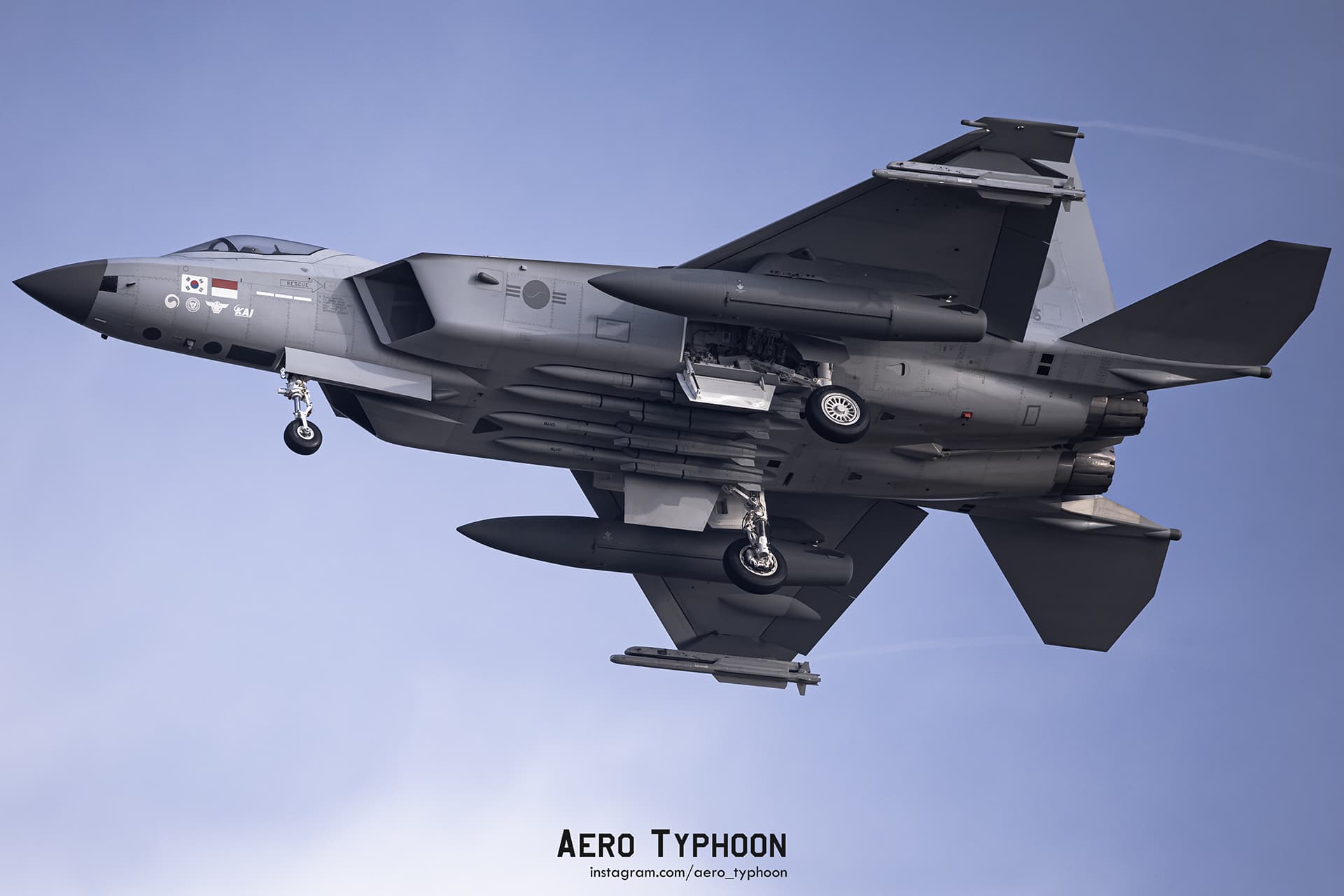
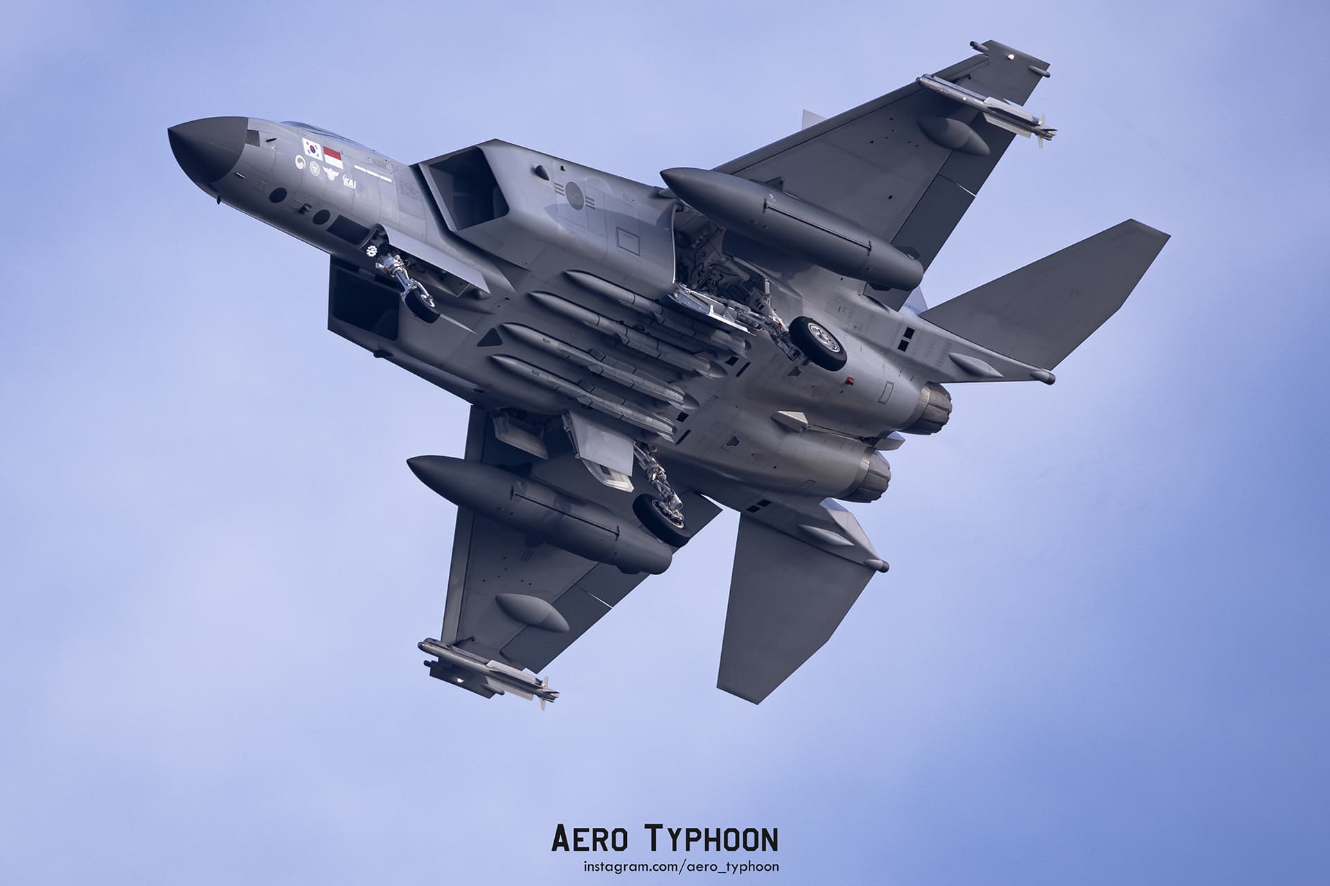
With the completion of the KF-21’s flight tests announced in January 2026, it grows ever closer to reaching introduction, with first roll out on March 2026, and expected service entry in September 2026 . With several potential clients in ongoing discussions, the KF-21 appears to be a unique addition to War Thunder. I hope to summarize what I’ve been able to compile, and hope to encourage discourse on an exciting new jet!
History & General Information
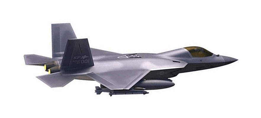
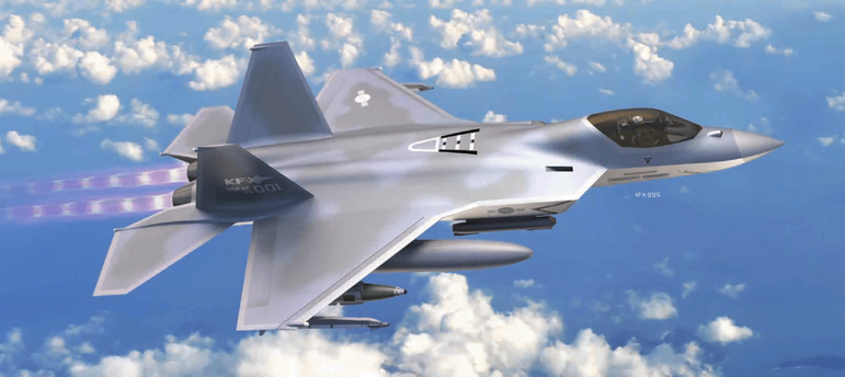
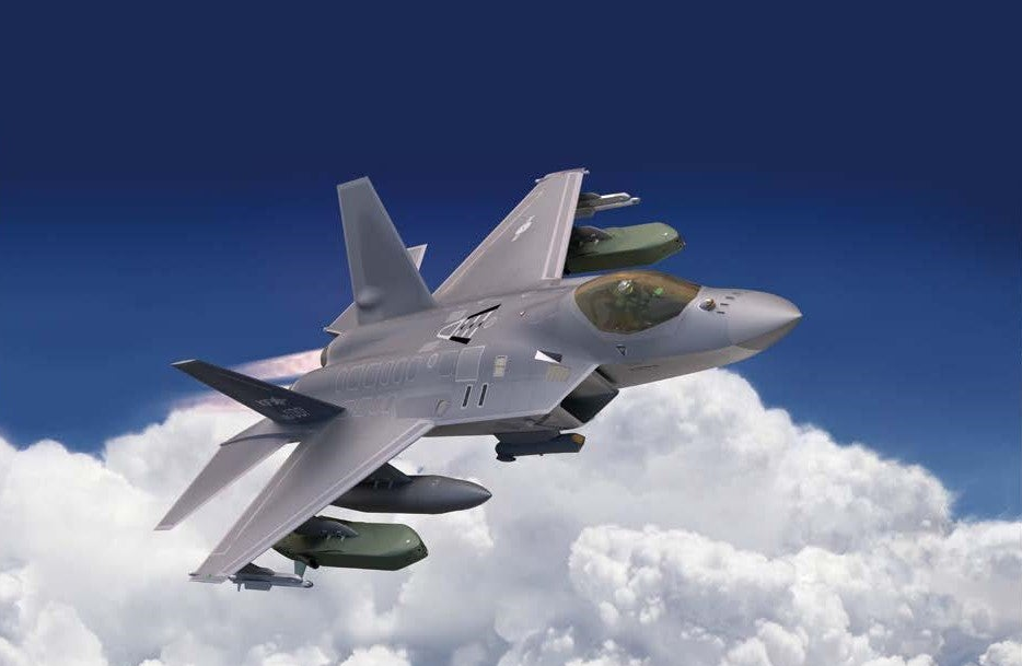
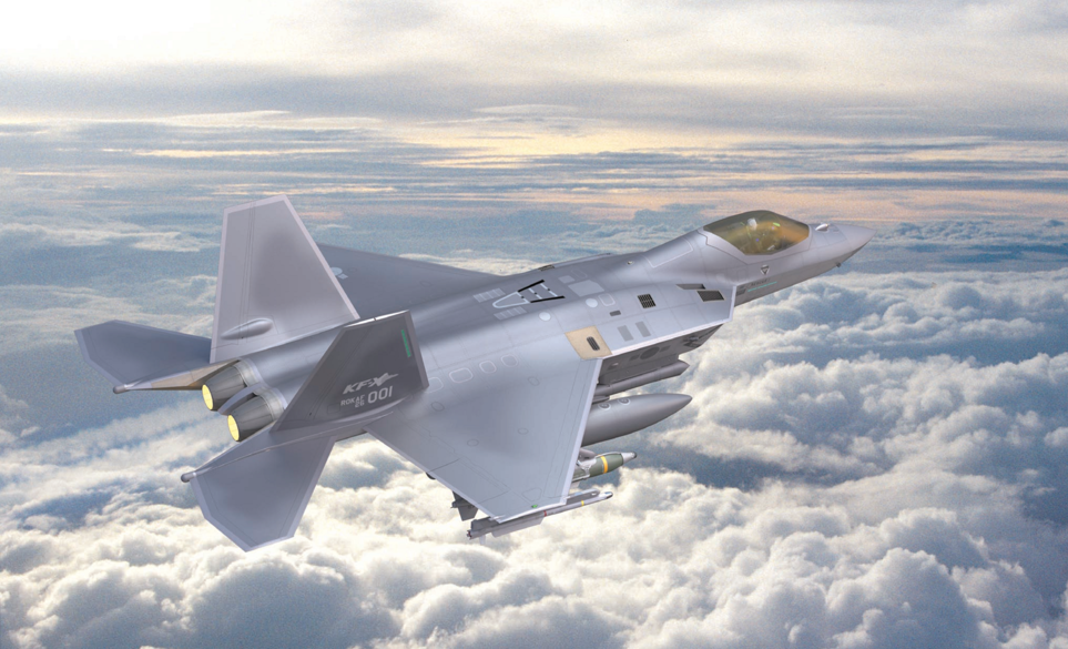
Originating from the Korean Fighter eXperimental (KF-X) development program, the KF-21 is a medium-weight “4.5” generation (+/++) designed to secure air superiority, perform long-range precision strikes and neutralize land and sea infiltration forces. Greatly responsible for the KF-X system’s development, Korea Aerospace Industries (Ltd.), or KAI (Ltd.), along with 16 domestic universities, 11 research institutes, and 553 partner companies participated in the KF-21’s creation.
The development of the KF-21 was envisioned to advance the industrial manufacturing capabilities of South Korea while preventing a power vacuum, as the Republic of Korea Air Force (ROKAF) intends to replace dated aircraft with an initial order of 120 aircraft, and a maximum of 250. Some KF-21s will be introduced as two-seat models for conversion training.
The KF-X project initiated under the pretense of domestically producing a multi-role fighter (MRF) jet to replace the dated F-4 Phantom IIs and F-5 Tiger IIs of the ROKAF. In 2002, the Joint Chiefs of Staff determined the R&D requirements of a Multi-role Fighter (MRF) and concluded the project was too ambitious. The Korean Institute for Defense Analyses (KIDA) supported this position, expressing doubts over South Korea’s ability to complete such a complex undertaking. Similarly, the ROKAF had concerns regarding vulnerabilities in future operational readiness should delays or failures occur.
Fraught with delays and postponement as the feasibility and economic cost were debated, renewed interest in the KF-X program arose. A study published in 2008 and incidents with North Korea throughout 2010 concluded the KF-X program was a matter of national importance.
Due to the risks of undergoing a modern domestic MRF program with little experience, the significantly high cost per-unit, and possible lack of foreign competitiveness, an international partner was required to mitigate the financial burden. Initially, South Korea offered Turkey a 20% stake in the KF-X program, however declined after seeking greater control over the initiative. Alternatively, Indonesia agreed to fund the 20% stake through Indonesian Aerospace and purchase 50 of the planned 150~200 units. In 2024, Indonesia’s stake was renegotiated to 7.5% stake. On July 15, 2010, South Korea and Indonesia formalized their partnership, with KF-X expected to target deliveries in 2026.
Prototypes and Pre-Production
C100
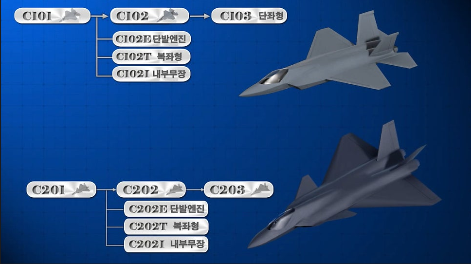
Since 2004, the Agency for Defense Development (ADD) has been conducting research on the design technology of fighter-class aircraft, accumulating data through Digital Mock-ups (DMU) and Wind Tunnel testing using Scale models. Experiments on the effects of leading-edge flap bending on an aircraft’s supersonic cruise capability, scheduling laws, and aerodynamic design lead to the C100 series, utilizing a diamond wing configuration, and the C200 series, utilizing a canard-delta wing configuration.
C103 and C104
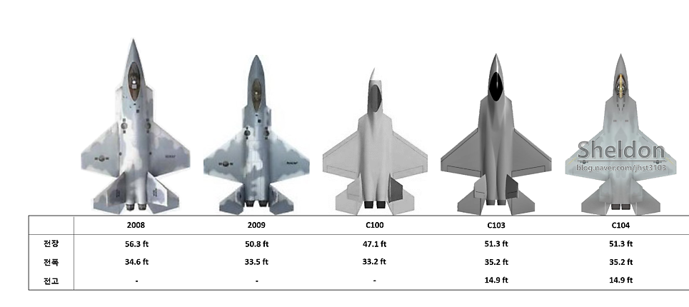
Derived from the results of preliminary research, the C100 and C200 design evolved into C103 and C203 through exploratory development conducted between 2011 to 2012. With the ongoing F-X Fighter program in Phase 3, the selected order for foreign purchase would determine the selected domestic fighter design for the KF-X Program. If an American fighter was selected, the diamond-wing C103 would be adopted. If a European fighter was selected, the canard-delta wing C203 would be adopted.
The F-35’s selection resulted in the elimination of the canard-wing C203. Competition between the C501, a derivative of the single engine C102E, and C103 resulted in the C103’s selection. The 290th Meeting of the Joint Chiefs of Staff set the operational requirements capability (ROC) revised for preference of a twin-engine type aircraft. Though contentious, the C103 design was ultimately adopted. Following the necessary revisions outlined in system’s development plan, the C104 was developed as a more mature C103.
C105
The C105 was developed based on the C104, reflecting improvements in intake performance, improved forward fuselage cross-section shape, and improved vertical fin/fuselage fastening structure. With an engine selection confirmed, the air intake was enlarged and optimized to match the engine intake flow rate, and the wing and tale areas enlarged to reduce wing surface load, improving the ability to secure excellent turning ability. Additionally, the front landing gear, which folded forward during exploratory development, was changed to fold backward during the system development phase. Further changes to the internal layout of equipment are suggested to have occurred, as well.
C106
Based on the C105, a scale model was manufactured with rotary balance (Germany BAR LAMP), subsonic force & moment (Korea Aerospace Institute [KARI]), transonic force & moment (UK ARA TWT), and supersonic force & moment (France ONERA S2MA) tests were conducted. Problems such as insufficient deep stall recovery ability, insufficient lateral/ directional stability, resulting in insufficient instantaneous turn rate and reduced maximum flight speed due to increased supersonic drag were identified during testing.
The C106 was developed with additional improvements, including more securitized internal fuel, improved handling stability, improved internal layout, and changes to the forward fuselage allowing reduction of drag. The larger fuselage size of the C106 configuration led to a corresponding increase in weight. To achieve a weight reduction of more than 500 kg below the Not To Exceed (NTE) target weight of 12.1 tons, rigorous weight management and structural design optimization were implemented.
C107
Further testing of the C106 revealed the lateral/directional stability characteristics became unstable and the deep tall recovery ability was insufficient in a specific angle of attack region. Research was undergone to develop a shape with excellent static lateral/directional stability characteristics in the high angle of attack region. Wind tunnel tests conducted on the combination of forward fuselage shape, wing shape and position, and vertical stabilizer shape and position, and based on the wind tunnel test results, the directional stability characteristics were improved by moving the wing rearward. Additionally, the deep stall and lateral stability characteristics were improved by moving the vertical stabilizer outward, and the directional stability characters were improved by moving it further forward.
The C107 possesses a vertical fin shape changed from a high-taper to a diamond shape, improving the lateral and directional stability, and a glove shape was added to the leading-edge flap of the main wing. The air intake was tilted at 10° dihedral angle to optimize intake performance, and the locations of the machine gun, integrated electronic warfare system’s Radar Warning Receiver (RWR) antenna, Electronic Countermeasure (ECM) antenna, Infrared Search and Track (IRST), and sensors such as the Electro-optical Targeting Pod (EOTGP) were determined. The design reflected the boundary layer separator on the side of the intake and the ram air intake for cooling equipment such as the Environmental Control System (ECS).
C108
The transition to the C108 required the layout of subsystems like the Auxiliary Power Unit (APU) exhaust outlet and control surface actuators be concretized. The glove added in the C107 was removed after wind tunnel testing and optimization, with the vertical fin shape changed to a symmetrical one. The RWR antenna, previously located on the vertical fin, was relocated to the wing tip of the main wing, and an IFF antenna was added forward of the IRST, and an ECM antenna was added to the sides and underbody.
C109
The final configuration, or C109, represents design improvements to achieve a better flutter margin. Achievement of a better flutter margin, a vibration phenomenon occurring in the wings and fuselage of an aircraft allowing enhancement of an aircraft’s aeroelastic stability, enables more stable maneuvering under high- speed, high-angle-of-attack conditions. Part of the horizontal stabilizer’s trailing edge was cut off, and the flaperon was split in two to save weight and improve the flutter margin. The vertical stabilizer covers the engine after its movement rearwards. This improves the low observability of infrared sensors from the side and improves the protection of the ECM antenna radome from flames. A natural ventilation structure design was reflected by forming a vent between the two engine nozzles, which utilizes the low pressure generated between adjacent nozzles when the engines are in operation, and atmospheric sensors, conformal antennas for communication/navigation, and lights for night operations were additionally reflected.
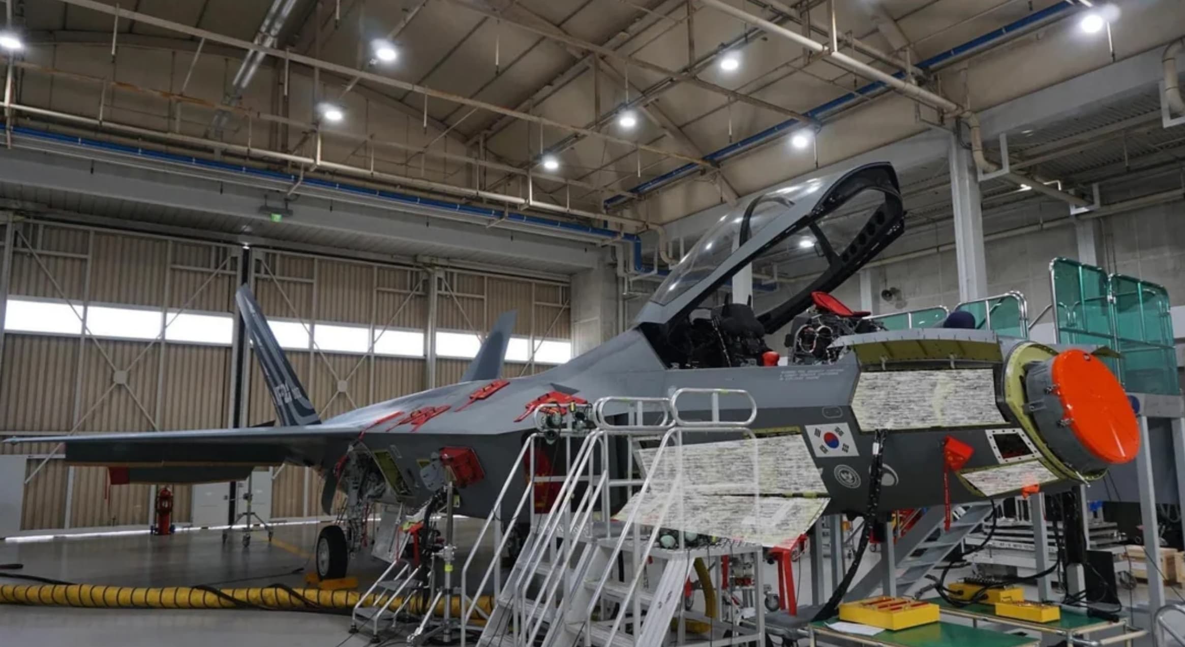
Block 0: The Prototype Batch
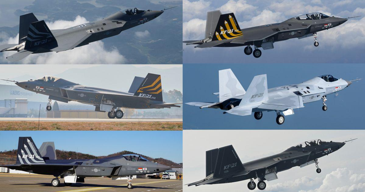
In 2019, using C109 as their base, 6 prototype units of “Block 0” were produced for flight trials between 2021 and 2025. Units 001, 002, 003, and 005 were single-seat units, while Units 004 and 006 were tandem-seat units. As a means of maintaining schedule and reducing cost, all 6 units were prototypes were produced once all simulated studies were completed and for cross-verification in a multitude of tests in real flight conditions. The most identifiable change made throughout the flight test process was the flattening of the sharp, angular sides of the inboard tail booms next to the engine nozzles.
Specifications, Features, and Performance
Designed to fulfill the requirements of structural strength and durability to withstand high maneuvering loads in transonic and subsonic ranges, the KF-21 secures excellent combat maneuverability through high lift-to-drag ratio in a wide flight envelope, enabling performance of various missions with high angle of attack characteristics. Smaller than the F/A-18E/F while using the F414-GE-400, the KF-21’s thrust -to-weight ratio is more comparable to the Eurofighter Typhoon. The KF-21’s wing loading is lower than the F-35 while maintaining similar thrust.
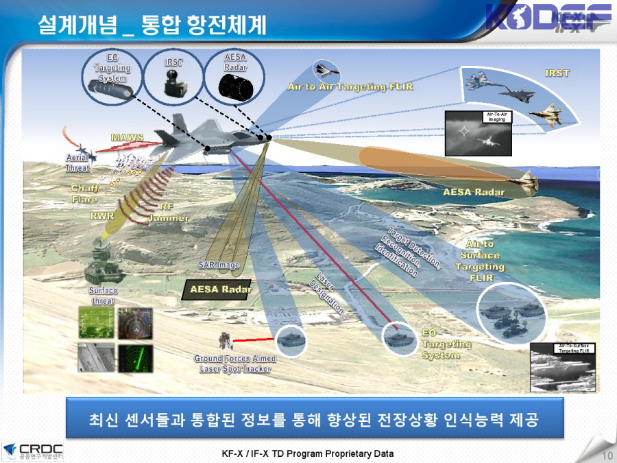
To fulfill the requirements of a 4.5 generation (+/++) in a timely and cost-effective manner, KAI and the ADD opted for a Dual-path approach involving the indigenization of key components wherever possible and utilizing proven international expertise wherever necessary. As such, an outlined localization rate of 65% was determined for the KF-21. Despite the Dual-path approach, four major technologies required indigenous development, in some capacity, after failure to achieve approval for transfer from the United States: The IRST, the Radar, the Radio Frequency Jammer (RF Jammer), and the Electro-optical Targeting Pod (EOTGP).
Engines
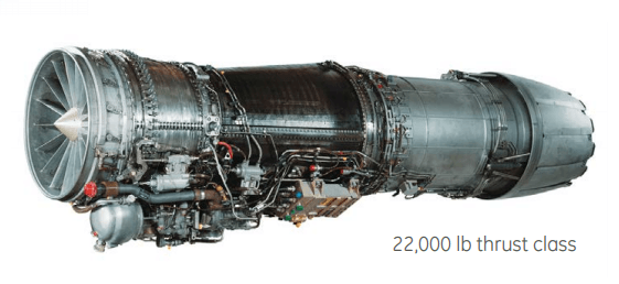
In need of an interim engine for use until the development of an indigenous system, the KF-X program, among other options, such as the F404, received highest contention between the EJ-200 and the F414 for selection. On May 26, 2016, General Electric’s F414 was selected. On July 12th of the same year, Hanwha Techwin and GE Aviation signed a technology collaboration agreement for the domestic manufacture of engine parts to power the KF-X aircraft. Adopted as the KF-21 engine, the F414 engine operates in the 22,000 lb. (98 kN) thrust class. The 2 F414 engines provide the KF-21 of a Thrust-to-weight ratio between 1.1~1.15; this assumes a fuel load of ~100% capacity and a clean armament loadout. Manufactured under license by Hanwha Aerospace, the F414 achieves a localization rate of 39%.
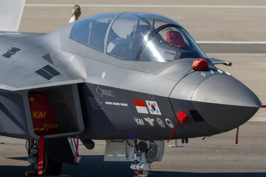
Cockpit
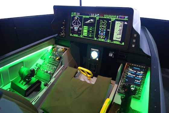
Similar in design to the F35’s, the KF-21 uses a glass cockpit equipped with a LAD (Large Area Display) with a 20 x 8-inch low-reflection resistive touch display. The LAD selectively displays essential flight data, aircraft data, and mission-related information required for the pilot to perform their mission. Offering threat information fed from integrated electronic warfare equipment and target information through sensor fusion, the pilot is informed of the optimal response method.
The LAD uses a custom LCD panel with a resolution of 2560 x 1024 with LED backlight, being internally composed of two panels with a resolution of 1280 x 1024. It is configured to appear as a single panel to the user. The CPM uses Freescale’s T2080 processor, is equipped with a Real Time Operating System (RTOS), and runs an Operational Flight Program (OFP). The General Processing Module (GPM) allows generation and output of graphic symbols, and the graphics processor uses the AMD Radeon E8860.
The LAD incorporates redundant design and health monitoring technology to enhance reliability. The system is designed to operate without interruption even if one of its two DC 28V inputs fail. A hot standby function is present, allowing the remaining display computer to take over in the event of failure.
An Intelligent Platform Management Controller (IPMC) monitors the health of integrated systems. Measuring the input voltage and current supplied to the module, output voltage, and board temperature, the IPMC detects module abnormalities and transmits the information to a higher-level processor or network. The collected data is then used to isolate each module to prevent secondary failures and switch to the master display computer depending on the severity of the abnormality.
The HUD utilized by the KF-21 is developed by LIG Nex1, with ELTA’s JHMCS-II as the HMD. The KF-21 features Hands-on Throttle and Stick (HOTAS) multi-function joystick and Direct Voice Input (DVI) technology, allowing voice control within the cockpit. The mission computer adopts the Integrated Modular Avionics (IMA) architecture and is designed with an open architecture based on ARINC-653, and the OFP is modularized for ease of maintenance, stability, and performance improvement. Initially, Link-K was considered for the tactical data link terminal, however the development schedule made initial integration of the Link-K terminal and technical data for KF-X aircraft in a timely manner impossible. Link-16 was developed as a priority, with the Link-K terminal applied in the mass production units.
Radar
Denoted as APY-016K, the radar of the KF-21 was developed by the Agency for Defense Development (ADD) and Hanwha Systems. As an active electronically scanned array (AESA) multi-function radar (MFR), APY-016K is mounted on the fuselage at a 15-degree angle to reduce RCS and consists of 1,088 T/R modules. The T/R module consists of four channels, producing more than 13 W of peak power per channel in the X-Band frequency band and more than 18 W of peak power per channel based on the center frequency, with a 6-bit digital phase/amplitude control function.
The APY-016K’s detection range is from -45° to +70° in elevation and ±70° in azimuth, with a detection/tracking range of approximately 150~200 km per 1m2 of radar cross-section (RCS). It supports air-to-air and air-to-ground simultaneous search modes, air-to-ground SAR mode, simultaneous air-to-air/air-to-ground/air-to-sea detection/tracking functions and electronic warfare functions, LPI mode, air-to-ground ATR (Automatic Target Recognition) and air-to-sea ISAR functions, non-cooperative target recognition (NCTR), wideband data link, and mutual interference cancellation of the same type of radar signals. The system’s localization rate is 89%.
IRST
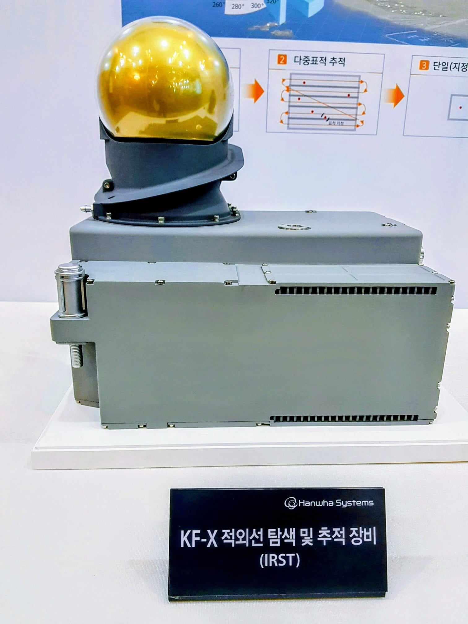
With a localization rate of 37%, the Infrared Search and Track (IRST) mounted on the upper right of the forward fuselage was developed based on the hardware of Leonardo’s Skyward IRST. The detection performance was improved by applying a dual-band infrared detector simultaneously detecting mid-wave infrared (MWIR) and far-wave infrared (LWIR). The IRST is capable of wide-band search, multi-target tracking, single-target precision tracking, FLIR image generation to assist the terrain avoidance mode of the AESA radar.
EOTGP
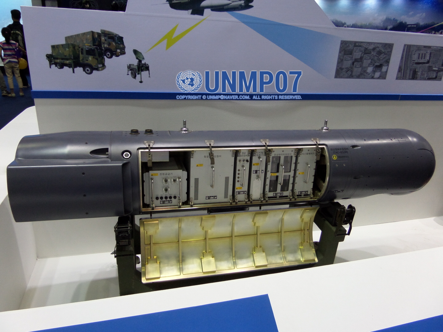
The KF-21’s Electro-optical Targeting Pod (EOTGP) uses an SXGA (1280 × 1024) cooled infrared detector that detects the MWIR band, with a pixel size of 15μm and InSb (Indium Antimonide) as the detection material. With a localization rate of 82%, the EOTGP is also used in air- to-air missions and can detect enemy aircraft more effectively through IRST and sensor fusion.
Electronic Warfare Suite
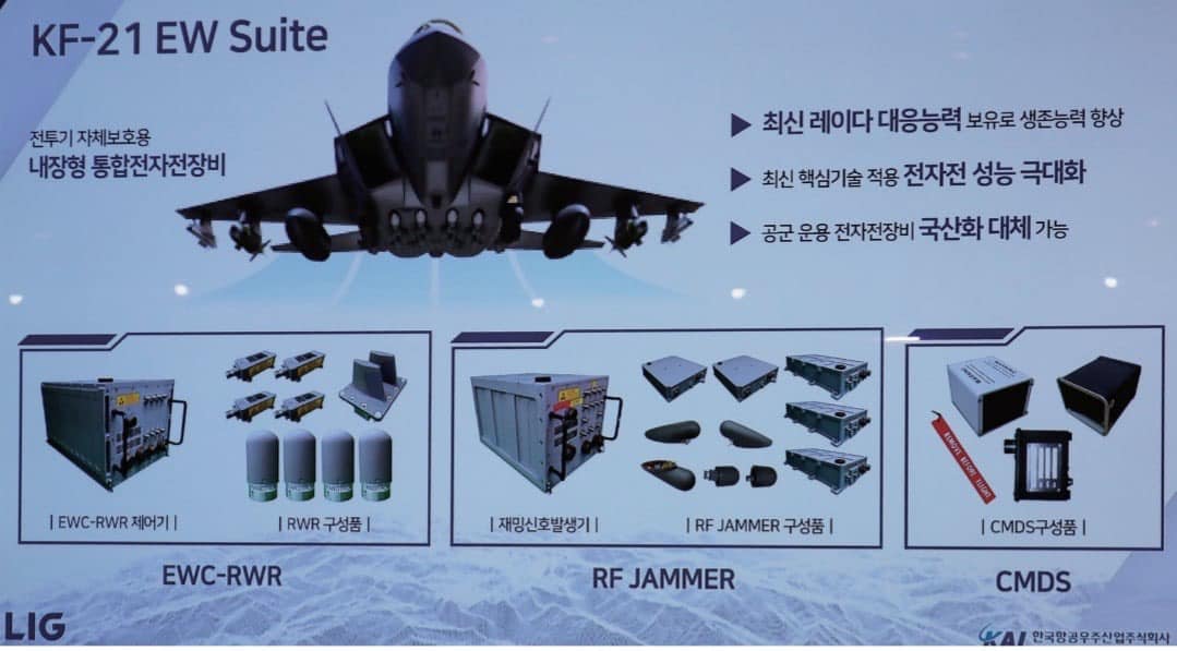
The KF-21’s integrated electronic warfare (EW) suite, or KF-21 EW Suite, consists of a radar warning receiver (RWR), electronic countermeasures (ECM), and a chaff/flare dispenser (CMDS), with a domestic production rate of 77%. With 6 CMDS, each with 30 “normal size” countermeasures. Installed on the around the rear of the aircraft, the KF-21’s CM count is 180 “normal size” countermeasures. The embedded ECM was developed based on the ALQ-200K electronic warfare pod. Key components, such as a wideband digital receiver that precisely measures specifications at high speed and a DRFM that stores, restores, and generates signals across a wide bandwidth, were designed and manufactured in the form of cards using the latest technology to reduce size and weight. These components were redesigned to enhance amplifier output and widen the antenna beamwidth, enabling wide-area jamming.
The KF-21’s EW suite can receive and analyze wideband RF signal information across the C~J-Band, generate jamming signals for E~J-Band against multiple threats. The EW suite can use deception/noise/composite jamming techniques to identify and disrupt various radars, including AESA radars.
Stealth Capabilities
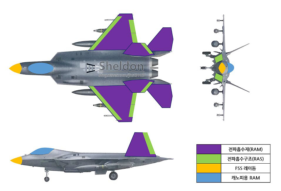
To ensure survivability in future battlefields, the KF-21 required a low-observable shape design including a reflective angle alignment, a flush-mounted antenna, S-Duct, a flat fuselage, and a semi-recessed weapons bay. Currently, an RCS lower than the F/A-18E/F Super Hornet’s is achieved by the KF-21. RAM is applied to the canopy, wings, and tail, while RAS is applied to the ducts and flaps inside the fuselage. Frequency-selective surface technology is applied to the radome to prevent reflection of enemy radar waves back on the antenna. Some RCS reduction designs such as sawtooth treatment and conformal antennas were not applied, and factors increasing RCS such as external weapons and external targeting pods, result in a low-observable performance at the Reduced Observable level (RO-level).
Like the Fiber Mat technology of the F-35, the film/prepreg RAM developed for the KF-21 is a laminated radio-wave absorbing material cured on carbon fiber composites. Instead of conventional nickel-coated carbon fibers, the world’s first iron-based magnetic metal coating technology was developed to achieve low cost while delivering high electromagnetic wave absorption.
Models and Variants
Block I
Part of the initial mass production between 2026 and 2028, Block I units perform air-to-air missions. The current production volume is estimated at 40 units.
Block II
Block II allows operations of air-to-ground and air-to-ship weapons. Additional weapons systems will be integrated throughout the weapons testing conducted between 2026 and 2028. Block I units are designed to be upgraded to Block II standard. Eighty aircraft are scheduled for deployment in the second phase of follow-on production between 2028 and 2032.
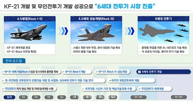
Block III
Advertised as a “5.5” (+) generation aircraft, the Block III, KF-21EX/EJ, or KF-X successor, is scheduled for launch after the 2030s. The Block III is expected to feature various new technologies that can enhance mission performance in future battlefields, such as RF/IR composite stealth technology, microwave scattering control metasurface technology, AESA radar performance improvement, embedded EOTS, wing-mounted ultra- wideband AESA antennas, next-generation electronic warfare systems, next-generation survival systems such as DIRCM, a 250kW-class high-power density starter/generator, and MUM-T (Manned-Unmanned Teaming) an unmanned aerial vehicle remote control system for collaborative missions between manned and unmanned aircraft. Due to the presence of a planned internal weapons bay in all blocks of KF-21 airframes, the current assumption is, all units may be upgraded to the Block III standard.
Armament
The armament of KF-21s are subject to change due to the platform still undergoing approval/integration of some planned export equipment and certain systems being under development. The following listed armament will be identified based on level of confirmed integration: [!] = Fully Integrated, [!] = Approved and Will be Integrated, [!] Planned for Integration or Still in Development.
- M61A2 20mm Gatling Gun [!]
- IRIS-T [!]
- Meteor [!]
- AIM-120 [!]
- AIM-9X [!]
- SPEAR [!]
- Brimstone [!]
- Indigenous SRAAM [!]
- Indigenous LRAAM [!]
- Indigenous Hypersonic Anti-Ship Missile [!]
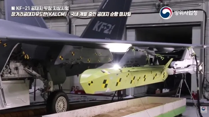
- KALCM [!]
- Al-Tariq [!]
- KGGB [!]
- AGM-65 [!]
- GBU-12 [!]
- GBU-31 [!]
- GBU-38 [!]
- GBU-39 [!]
- GBU-53 [!]
- GBU-54 [!]
- GBU-56 [!]
- CBU-105 [!]
- Mk. 82 [!]
- Mk. 84 [!]
KF-21 Hardpoints outlined during KF-X’s Exploratory Development Phase
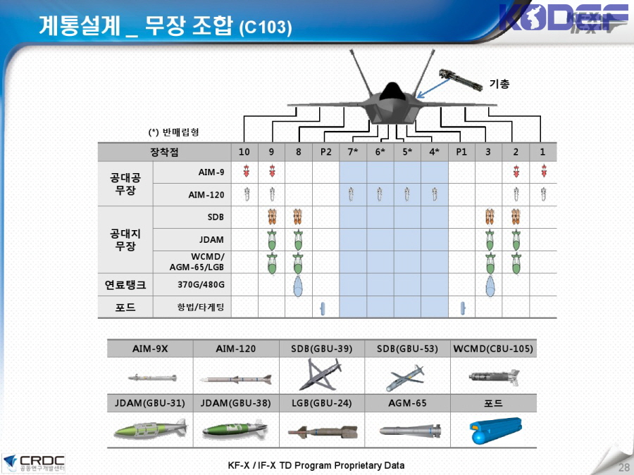
Note: This chart is from early in the KF-21’s development and does not represent the actually possible loadouts of the aircraft. It’s use should be more for providing an idea regarding the armament of the aircraft.
KF-21 Weapons Capability
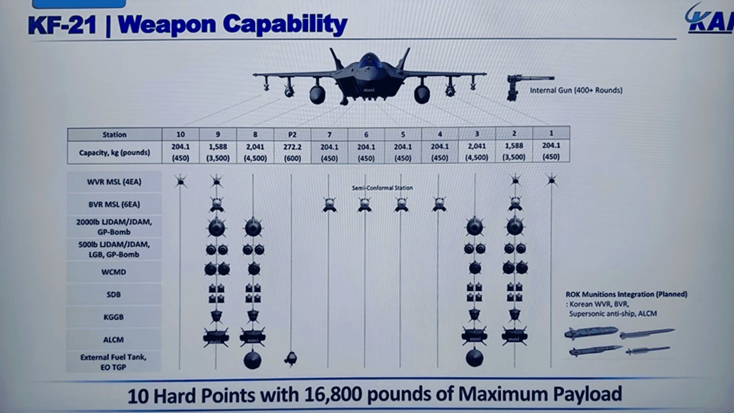
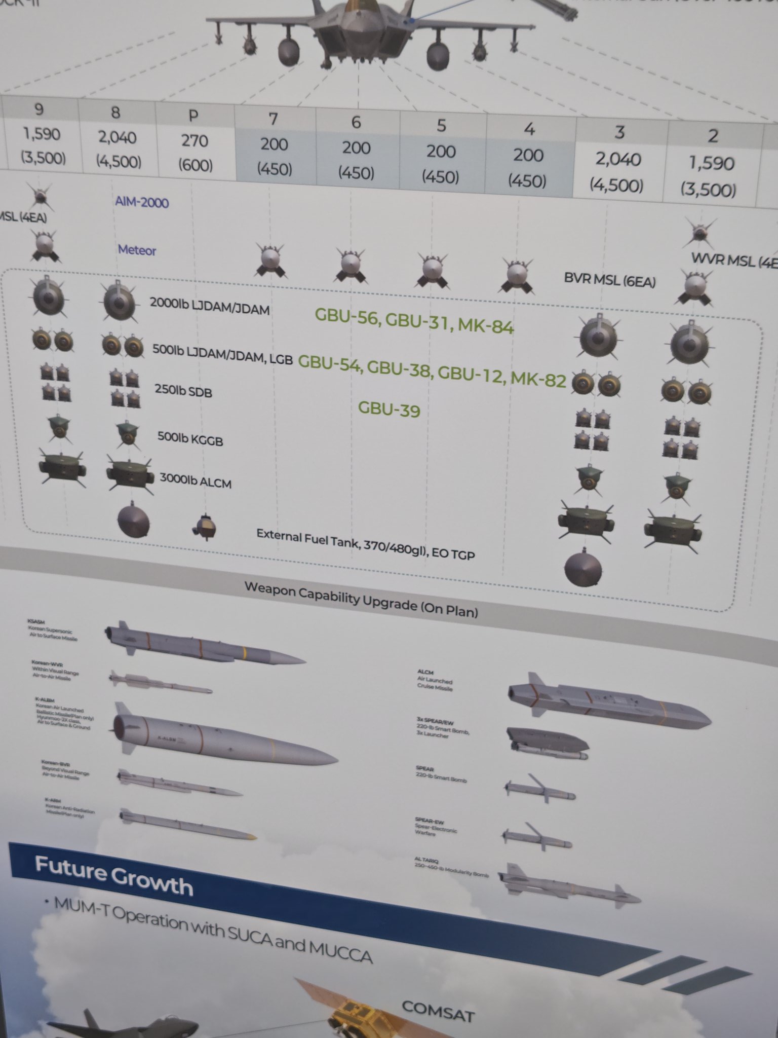
Note: These charts represent the more finalized armaments integrated and/or planned for deployment on the KF-21. Due to the nature of certain munitions still undergoing development, this is always subject to change. As such, these figures represent the most reasonable equipment for the KF-21.
Proposed Variants
KF-21N
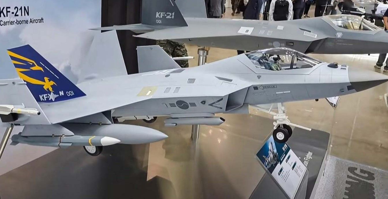
Showing interest in a larger aircraft for their CVX project, the Ministry of Defense determined such selection contingent on production of an indigenous maritime fighter jet. KAI unveiled the KF-21N as a model in September 2022 envisioning a carrier-based fighter with 20% larger wings than a KF-21. Making changes for CATOBAR and STOBAR operations, KAI claimed the KF-21N could be ready within a few years should the ROKN decide to procure a large enough aircraft carrier. A ship focused on control of unmanned vehicles was selected instead.
KF-21EA
Designed to serve as an electronic warfare aircraft, like the EA-18G Growler, the KF-21EA would feature tandem seating, assigning the rear operator as an electronic warfare officer.
KF-21SA
Supposedly, the KF-21SA is a variant specified for the export market, allowing modifications as requested by clients.
Suggestions: