- Yes
- No

Hello everyone, greetings from Brazil!
And forgive me for any grammatical errors, but I use the translator.
I didn’t find any suggestions for this tank, so I thought I’d open this topic to discuss it.
Due to the introduction of the T-64A here in the game, the first T-64 was a little forgotten, but I believe it would be a great 9.0
Excerpt from Domestic armored vehicles. XX century: Scientific publication: / Solyankin AG, Zheltov IG, Kudryashov KN /
Volume 3. Domestic armored vehicles. 1946-1965 - M.: LLC “Publishing House “Tseykhgauz””, 2010. - 672 pp.: ill.
The Object 432 tank was created in 1962_ _ . in Kharkov by the design bureau of the plant named after. VA Malysheva (chief designer AA Morozov) based on the latest achievements of science and technology of that time and had the highest combat properties among medium tanks mass-produced in the first post-war period.
Development work on the creation of the tank was set by the Decree of the Central Committee of the CPSU and the CM of the USSR dated February 17 1961_ _ . According to the resolution, the plant named after. Malyshev of the Kharkov Economic Council was obliged to redesign, according to the technical specifications agreed with the USSR Ministry of Defense, the medium tank “Object 430”, which was developed in accordance with the Resolution of the USSR CM dated May 6 1955_ _ . ensuring the installation of modern cannon weapons on it, increasing the average speed to 45 km/h , as well as strengthening its anti-nuclear and anti-cumulative protection.
In June 1961_ _ . The technical design of the tank developed by the plant, designated “Object 432,” was reviewed at a meeting of section No. 7 of the HTC GKOT and at the plenum of the Scientific and Technical Committee of the GBTU. In March 1962_ _ . Factory tests of the first prototype of the tank began. In May 1962_ _ . The plant produced a second prototype of the tank for factory and field testing. In February 1963_ _ . Taking into account the results of factory tests of the first two prototypes, a third prototype of the “Object 432” tank was manufactured for field testing. In February-March 1963_ _ . In the troops of the Kiev Military District near the city of Chuguev , tests of the third prototype of the tank were carried out.
Based on the results of field and military tests of three prototypes on March 28 1963_ _ . The Decree of the Central Committee of the CPSU and the CM of the USSR “On preparation for serial production of a new medium tank /object 432/ and weapons for it” was issued. The first 10 tanks “Object 432” of the installation batch by the plant named after. Malyshev were collected by March 4 1964_ _ ., and by the end of the year the number of manufactured tanks reached 90 units. IN 1965_ _ . The plant produced 163 Object 432 tanks according to the chief designer’s drawings. Conducted in August-September 1965_ _ . factory control tests of the Object 432 tank showed that the measures introduced into the tank design to improve the reliability of the engine, gun loading mechanism and weapons stabilizer did not ensure defect-free operation within the warranty mileage of 3000 km . During 1966_ _ . The plant carried out design and production modifications to the Object 432 tank, taking into account factory control tests and experimental military operation of over 150 tanks. Total k 1966_ _ . The plant produced 294 Object 432 tanks. Resolution of the Central Committee of the CPSU and the CM of the USSR dated December 30 1966_ _ . The medium tank “Object 432” was adopted by the Soviet Army and was given the name “Tank T-64”. Serial production of this tank was organized in the city . Kharkov in 1966-1968 .
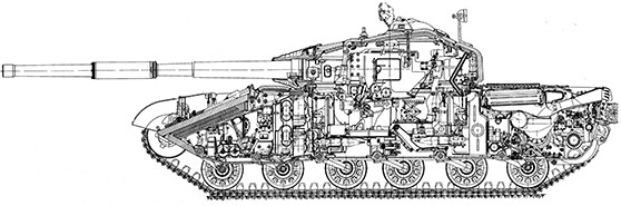
The Object 432 tank had a classic general layout with a separated crew of 3 people, placement of 1 15-mm cannon in a rotating turret and installation of a diesel engine across the longitudinal axis of the armored hull. A feature of the tank, which had a reserved volume 10.5 m3 _ , was a high density layout, as well as the smallest overall dimensions among medium tanks with a turret, especially in height ( 2.17 m ). This was achieved by eliminating the loader from the crew and using a loading mechanism, the low height of a specially designed engine and the presence of a stamping in the bottom of the hull to accommodate the driver’s seat. The internal equipment of the tank was located in three compartments: the control compartment, the combat compartment, and the engine-transmission compartment. The control compartment was located in the bow of the tank hull. In the center of the control compartment along the longitudinal axis of the body there was a driver’s seat. This arrangement made it easier to drive the tank. To the right of the driver’s seat, the right fuel tank and tank rack were installed, and to the left - the left fuel tank and batteries with starting and control equipment .
The seat was fixed in two positions: lower (when driving a tank with a closed hatch) and upper (when driving a tank with an open hatch). The design of the seat is provided for adjustment in height and along the body of the tank to install it in a position convenient for the driver. In front of the driver’s seat, on the bottom of the body, steering control levers, a fuel pedal, a gearbox release pedal (transmission pedal) and a brake pedal were installed. To the right of the driver’s seat, a gear selector (gear shift lever) was installed on the bottom. On the upper inclined nose plate of the hull in front of the driver’s seat there was a GPK-59 gyro-compass , which ensured that the tank was driven along a given course in conditions of difficult orientation.
To observe and drive the tank in a combat situation, the driver’s workplace was equipped with three prismatic viewing devices, which provided the driver with visibility in the 192° sector. The observation devices had electrically heated entrance and exit windows.

Combat weight - 35 tons; crew - 3 people; weapon: gun - 115 mm , machine gun - 7.62 mm ; armor - anti-ballistic; diesel power ( 700 l .With.); maximum speed - 65 km/h .
When driving the tank at night, instead of the central prism viewing device, a TVN-2BM binocular night vision device was installed in the shaft. Cleaning the driver’s viewing devices from dust, dirt, snow, etc. was carried out using a hydropneumatic cleaning system.
Above the driver’s seat in the turret plate of the hull there was a driver’s hatch. The armored hatch cover was opened and closed using a closing mechanism, which ensured the opening and closing of the hatch from both inside and outside the tank. At certain positions of the turret, the driver’s hatch did not open. The position of the turret at which the opening of the driver’s hatch was ensured was depicted by red arcs on the internal scale of the azimuth indicator of the turret rotation mechanism. When the stabilizer was working, the driver could turn the turret by turning on the toggle switch to a position that ensured the opening of its hatch. With the driver’s hatch open, rotation of the turret from the electric drive was eliminated by opening the electric drive circuit using a microswitch .
Behind the driver’s seat in the bottom of the hull there was an emergency exit hatch, the lid of which opened into the tank.
In the fighting compartment, located in the internal volume of the turret and in the middle part of the tank hull, to the right of the gun there was a workplace for the tank commander, and to the left for the gunner. At the tank commander’s workplace, a combined (day and night) commander’s observation device TKN-3 and two prismatic observation devices TNP-160 were installed in the rotating roof of the turret. The gunner observed the battlefield during the day through the TPD-43B tank sight-rangefinder or the VNM periscope observation device, and at night - using the TPN1-432 night sight. For the safe operation of the tank commander and gunner when rotating the conveyor of the loading mechanism (M3) of the gun, a cabin was installed in the fighting compartment. The cabin, which was a cylindrical welded basket, was mounted on brackets to the upper shoulder strap of the turret and rotated with it relative to the tank hull.
The tank commander and gunner entered and exited through two hatches in the turret roof.

Field tests of the Object 432 tank.
The hatches were closed with armored covers. For communication between the fighting compartment and the control compartment, there was a hatch in the front part of the cabin along the longitudinal axis, which was closed with a removable shield. To ensure the movement of crew members from one compartment to another, two trays were removed from the M3 conveyor.
In the rear of the tank, behind a sealed partition, there was an engine-transmission compartment, which, due to its exceptionally dense layout, occupied the entire volume 2.62m3 _ _ . The latter was achieved due to the central transverse arrangement of a two-stroke diesel engine with a horizontal cylinder arrangement and two crankshaft outputs in combination with two planetary onboard gearboxes, as well as through the use of an ejection cooling system for water and oil radiators .


The main weapon of the tank was a 115-mm smooth-bore D-68 tank gun, stabilized in two planes, with separate case loading, with a wedge semi-automatic bolt of horizontal movement and an ejection mechanism for cleaning the barrel bore from powder gases after firing. Direct shot range at a high target 2 m armor-piercing sub-caliber projectile was equal to 1870 m , cumulative - 990 m . When firing direct fire, a TPD-43B monocular, stereoscopic sight-rangefinder with independent stabilization of the field of view in the vertical plane was used. The greatest effective firing range of an armor-piercing sub-caliber projectile was 4000 m , high-explosive fragmentation and cumulative - 3300 m . Range measurement error in the range of 1000- 4000 m was from 3 to 5%. When firing at night, the TPN1-432 night monocular periscope sight was used, and when firing from a cannon from closed firing positions, a side level and an azimuth indicator were used. The largest effective firing range (using a night sight) with an armor-piercing sub-caliber projectile - 800 m .
The cannon was fired using a galvanic igniter or a mechanical (manual) trigger. The electric trigger was carried out by pressing a button located on the right handle of the remote control of the TPD -43B sight-rangefinder, or a key located on the handle of the flywheel of the gun’s lifting mechanism. Mechanical (manual) release was carried out by pressing a lever that extended outside the left shield of the gun fence. The vertical aiming angles of the gun using a hydraulic lifting mechanism ranged from -6 to +14°.
The rotation of the tower in the horizontal plane was carried out using one of two rotation mechanisms. When the electric drive was operating, the turret was rotated by a hydraulic rotation mechanism, and when the electric drive was not working, by a manual rotation mechanism. The horizontal aiming speed with the electric drive running ranged from 0.05 to 18 degrees/ s ; with a manual drive, it depends on the intensity of rotation of the flywheel with the handle of the turret rotation mechanism. An azimuth indicator was placed in the flywheel of the manually driven turret rotation mechanism. Locking the turret relative to the tank hull in any position was ensured by a turret ridge lock with eight
teeth. The gun in the stowed position was locked using a special three-position rod, which made it possible to fix the gun in the vertical plane relative to the turret in three positions.
The cannon could be fired with armor-piercing sub - caliber ZBM5, cumulative ZBK8, ZBK8M or high-explosive fragmentation ZOF17 shells. Armor penetration of BPS at range 1000 m amounted to 250 mm ( 135 mm at an angle of 60°), and KS - 450 mm .
A 7.62-mm PKT machine gun was paired with the cannon, which ensured effective destruction of openly located targets at a distance of up to 1500 m . To fire a machine gun, it was necessary to press the button on the left handle of the TPD-43B sight-rangefinder control panel or the button on the handle of the flywheel of the turret rotation mechanism.
Effective firing immediately from a cannon and coaxial machine gun was ensured by the 2E18 “Siren” stabilizer, which had electro-hydraulic drives for stabilizing and aiming the cannon and coaxial machine gun in the vertical and horizontal planes. In addition, the stabilizer provided target designation from the tank commander to the gunner in the horizontal plane and emergency rotation of the turret from the driver’s workplace. Three-degree gyroscopes, which had the property of maintaining the direction of their axes in space unchanged, were used as the master elements of the stabilizer in the vertical and horizontal planes.
To ensure the combat rate of fire of a tank gun up to 10 rounds /min. the tank was equipped with a loading mechanism (M3). It was a hydroelectromechanicalcomplex with a rotating conveyor, a feed mechanism, a mechanism for catching the charge pan after a shot, and a dispensing mechanism. The loading mechanism ensured automatic loading of the gun with three types of shots with BPS, KS and OFS in a separate-case version. The M3 conveyor capacity was 30 rounds. Loading angle (constant) - +2°48’. Conveyor rotation speed is 24 degrees/s. The duration of loading one shot depends on its location in the M3 conveyor relative to the feed mechanism lever. The minimum duration of loading one shot was 6 s, the maximum (full turn of the conveyor) was 20 s .
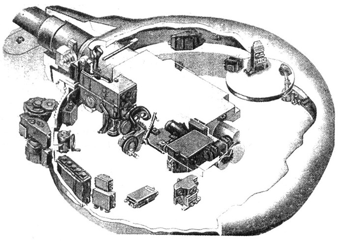
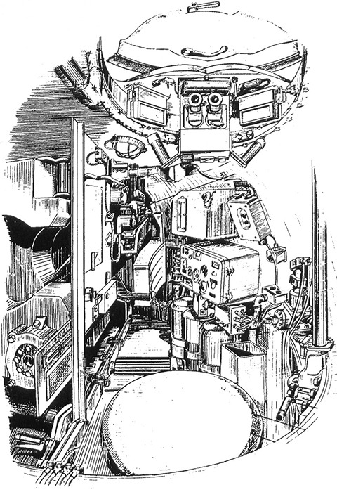

Diagram of the loading mechanism of the “Object 432” tank: 1 - charge pallet catcher; 2 - copy; 3 - upper half-tray ; 4 - grips; 5 - lower half-tray ; 6 - feed mechanism lever trolley; 7 - feed lever; 8 - charge pallet catcher drive; 9 - conveyor of the loading mechanism.
Loading the gun could also be done manually with shots taken from the tank’s non-mechanized racks.
Inside the tank there were stowages for an AK-47 assault rifle, a 26-mm signal pistol and 10 F-1 hand grenades.
The ammunition for the cannon consisted of 40 rounds, for the PKT machine gun coaxial with the cannon - 2000 rounds, for the 7.62 mm AK-47 assault rifle - 120 rounds.
The tank’s armor protection is anti-ballistic. It provided protection for the crew and internal equipment from the effects of shells from foreign 105-mm rifled tank guns from a distance 500 m at heading angles of fire +20°.
Combined armor barriers were used in the design of the hull and turret. When operating in combat conditions, side panels (screens) were installed on the tank. Three right and three left side panels were attached to the left and right track shelves in the front of the tank. Two more (left and right) front flaps were attached to the front folding mud flaps.

The bow of the tank hull was welded from upper and lower inclined armor plates. The angle of inclination of the upper frontal part of the hull was 68 ° and it had a multi-layer combined structure. Between the outer and inner armor plates there were two sheets of fiberglass. This relatively lightweight material effectively weakened the cumulative jet and the flux of fast neutrons without causing a large increase in the mass of the tank hull. To reduce the likelihood of the tank turret jamming from ricocheting shells, bumpers were welded on the upper inclined sheet and on the side “cheekbones” of the front sheet of the tank hull roof.

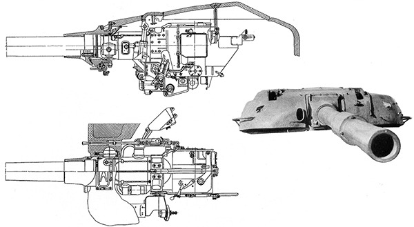
The design of the bow of the hull and the frontal part of the turret of the Object 432 tank
To ensure placement of the M3 conveyor in the fighting compartment with the maximum possible number of shots, stampings were made in the middle part of the vertically located armor plates on the sides of the tank hull . The stampings at the front were protected by armor plates welded to the outside of the sides. In the upper part of the stampings and overlays there were cutouts for the upper branches of the tracks.
The roof over the MTO was a welded structure made of rolled armor plates and cast sidewalls. To provide access to the components and assemblies of the power plant and transmission, the roof was raised upward at an angle of 29°30’ using a lever-torsion lifting mechanism . The bottom of the tank hull consisted of three armor plates welded together, each of which was a stamped part with a trough-shaped cross section. To compactly place torsion bars and increase structural rigidity, there were longitudinal and transverse stampings in the bottom. In addition, there was a stamping in the front bottom sheet, which provided the necessary height to accommodate the driver in combat mode.
The projectile -resistant cast turret had a powerful frontal section with a closed perimeter embrasure for the gun and holes for a machine gun and a rangefinder sight. In the right and left halves of the frontal part of the tower there were special cavities that were filled with aluminum alloy inserts. The roof and base tube housing of the sight-rangefinder were welded to the top of the turret . To the right and left of the gun embrasure, in front of the exit windows of the rangefinder sight , special cutouts were made in the turret to provide the necessary visibility.
The turret was mounted on the tank body on a ball bearing, which was an angular contact ball bearing, the rings of which were the turret shoulder straps. The upper shoulder strap of the turret support was also an integral part of the ball bearing of the conveyor of the gun loading mechanism. Between the turret and the lower shoulder strap, a rubber cuff was installed in the groove of the lower shoulder strap, which prevented the penetration of dust into the tank when the tank was moving, water during underwater driving, shock waves and radioactive dust during a nuclear explosion.
Protection of the crew and internal equipment of the habitable compartments of the tank from fast neutrons was ensured by installing a special material (lining) based on polyethylene inside the vehicle. Additional protection for the commander and gunner was also provided by vertically located charges of artillery rounds, and the driver - by diesel fuel, located in the left and right front tanks.
All these measures ensured a 16-fold reduction in the level of penetrating radiation.

Side flaps (screens) in the stowed position (top photo) and
in a combat (bottom picture) position.

Installation diagram of anti-cumulative side screens
The tank was equipped with an anti-nuclear protection system (PAS), which, together with the armor structure, provided protection for the crew and internal equipment of the tank from the effects of the shock wave of a nuclear explosion by sealing the vehicle with automatic closing before the arrival of the shock wave of holes that could be open under operating conditions (ventilation hatches, blinds over the radiator and air cleaner, etc.). A high level of sealing of the habitable compartments of the tank was ensured by permanently installed sealing devices and automatically closing additional sealing devices. Permanent seals had the gun and machine gun embrasures, the ball bearing of the turret, the MTO partition , the hatch covers for the crew members and the emergency exit, and the installation sites for observation and aiming devices. To protect the habitable compartments of the tank from the penetration of radioactive dust by creating excess air pressure (pressure) in them and providing the crew members with purified air, a supercharger was installed in the right rear part of the fighting compartment. The supercharger was a centrifugal fan with inertial cleaning of dusty air in the rotor. It ensured the creation of excess pressure of at least 0.29 kPa (0.003 kgf/cm 2 ) and air purification from dust by approximately 98%.
The main elements of the electrical equipment of the ESD system were the radiometric protection unit RBZ-1M, the X-ray meter DP-ZB, the supercharger motor, the KUV-5 fan and supercharger control box, the electromagnet of the engine stopping mechanism and the fuses of the squibs of the closing mechanisms. In the tank’s ESD system, special attention was paid to increasing the level of protection for the tank commander. During a nuclear explosion, the signal from the RBZ-1M radiometric protection unit was supplied to the KRPU relay box, and from it voltage was supplied to the squibs of the actuators. When the squib in a special mechanism was triggered, the seat, together with the tank commander, quickly fell down - under the protection of the thickest armor of the turret.
To extinguish the fire that broke out in the tank, a unified automatic, triple-action PPO system was used. The fire extinguishing composition “3.5” was contained in three two-liter cylinders. The system could operate in automatic, semi-automatic or manual mode. To extinguish minor fires in the tank there was an OU-2 manual carbon dioxide fire extinguisher.
An active means of camouflaging the tank was thermal smoke equipment (TSA), which provided, with the engine running, multiple deployment of smoke (aerosol) screens.
To overcome water obstacles up to depth along the bottom 5 m , the tank was equipped with OPVT. The tank’s equipment for underwater driving consisted of permanently installed and removable units. The following were permanently installed on the tank: seals for the hull and turret of the tank; sealing the gun’s armor protection; exhaust gas bypass damper; drive to the flue damper and to the air cleaner ejector seal valve and two water bilge pumps with a capacity of 100 l/min. When overcoming a water barrier, the following were installed on the tank: a two-section air supply pipe; two-section exhaust pipe; gun muzzle seal; coaxial machine gun seal; Exhaust valve; sealing the blinds above the air cleaner; air cleaner ejector seal; sealing ventilation holes M TO; valve for draining water from the flue; check valves of water pumps; clips for fixing the handle of the blinds drive lever. Removable OPVT units were placed outside the tank. The installation of removable parts of the OPVT by the crew was carried out within 45 minutes . After crossing the water obstacle, the time required to prepare the tank for immediate firing was only 1 minute. Movement along the bottom of the reservoir was carried out in 1st gear. Maintaining the given direction of movement was ensured by the operation of the GPK-59 gyro-semi-compass and with the help of radio communication. In addition, the OPVT kit included three isolation devices for the AT-1 tanker.
The basis of the tank’s power plant was a five-cylinder, two-stroke, turbopiston high-speed tank diesel 5TDF liquid-cooled with direct-flow purge, piston gas distribution, horizontal cylinder arrangement and counter-moving pistons. Maximum engine power weight 1050 kg was 515 kW ( 700 l . With .). Power take-off was carried out on both sides of the exhausted crankshaft. The axes of the engine crankshafts were located transverse to the longitudinal axis of the tank. The engine was mounted at three points using two rigidly fixed axles and one hinged support. The installation of the engine, unlike the installation of a V-2 type engine, did not require alignment with respect to the transmission units, due to which it was relatively easy to replace in the field.
The internal fuel tanks were filled with 815 l diesel fuel grade DL, DZ or DA. The capacity of the front group of tanks, consisting of the left and right front tanks and tank rack, was 505 l . On the left fender of the tank there were three external fuel tanks with a total capacity of 330 l . The outer tanks were welded from aluminum sheets and each of them had a filling neck that was closed with a stopper.

Fuel system of the “Object 432” tank: 1 and 9 - right and left front fuel tanks; 2 - tank rack; 3 and 4 - right and left aft fuel tanks; 5 - fine filter; 6 - engine fuel priming pump; 7 - coarse filter; 8 - external fuel tanks; 10 - manual fuel priming pump; 11 - fuel distribution valve.
The tanks were connected to each other in series. Fuel was produced from the tanks through the rear tank, the pipeline of which was connected to the shut-off valve of the external tanks. Thanks to the relatively low specific fuel consumption of 238 g/ kWh (175 g/ hp - h ) by the engine, the highway range at one refueling reached 650 km . To refuel the tank’s fuel tanks in the field, a fuel refueling device was provided. The device consisted of a bow centrifugal pump (when overcoming water obstacles it acted as a bilge pump), a switch valve (“water”, “fuel”), a filling fuel filter and a durite hose with an intake pipe and a rotary elbow with a fitting.

Placing a cassetteless air cleaner in the MTO of the Object 432 tank.

Layout diagram of MTO units: 1 and 5 - left and right final drives; 2 and 4 - left and right side gearboxes; 3 - diesel 5TDF.
The air cleaning system used a single-stage cassetteless cyclone-type air cleaner with ejection removal of dust from the dust collector. The air cleaner was installed on the left side above the air inlet pipes into the engine supercharger.
A full-flow fine centrifugal oil filter was used in the forced lubrication system of a dry-sump engine. The filter was located on top of the engine block and was attached to it with studs. A continuous supply of oil to the rubbing parts was ensured by a pressure oil pump. To create a given pressure in the system over a wide range of engine crankshaft rotation speeds, the injection oil pump had a capacity of 120 l/min. The filling capacity of the engine lubrication system was 75 l .
A feature of the liquid cooling system was the use of exhaust gas energy to create a flow of cooling air through the radiators. The use of an ejection cooling system in the air path ensured the compactness of the cooling system, its good self-regulation and a reduction in the amount of heat emitted by the tank. Two series-connected tubular-plate water radiators of similar design were installed in an ejector housing isolated from the MTO at an angle of 4° towards the nose of the tank. The tilt of the radiators ensured complete drainage of the coolant from them. The filling capacity of the cooling system was equal to 65 l . To cool the engine, water with a three-component additive was used in summer, and low-freezing liquid grade 40 or 65 was used in winter.

Onboard gearbox of the Object 432 tank.
Preheating of the power plant before starting the engine and maintaining it in a state of constant readiness for start-up at low ambient temperatures was carried out using a heating system, the main element of which was a nozzle heater. The engine and power plant components were heated by liquid, and the oil in the oil tank was heated by the exhaust gases of the heater. In addition, to facilitate engine starting, the air entering the engine cylinders was heated using electric torch heating.
The engine was started from two independently operating systems: from a starter-generator (main method) or from an air starting device (backup method). If necessary, the engine could be started in a combined way (simultaneously with a starter-generator and an air starting device) or from a tug.
The air launcher was part of the tank’s air system. In addition to starting the engine, this system ensured oil injection into the engine cylinders, operation of electric torch heating and cleaning of inspection devices from dirt and dust while driving and on the spot. The sources of compressed air were: an AK-150S compressor (with the engine running) and two compressed air cylinders (with the engine not running). The operating pressure in the system is 14.7 MPa (150 kgf/cm2 ) .
The mechanical planetary transmission ensured high average speed, good maneuverability and maneuverability of the tank. The high efficiency of the transmission contributed to a large power reserve, and the use of a hydraulic servo transmission control system made it much easier to control the movement of the tank. The transmission consisted of two (left and right) final drives, two final drives, a transmission lubrication system and a hydraulic servo control system. The design of the transmission ensured high operational reliability and did not require significant time spent on maintenance.

Idler wheel and tracks of the Object 432 tank.

Tank “Object 432” with an installed OPVT kit. At the top of the picture are the air supply and exhausted pipes in the transport position.
T-64 (Object 432) has autoloader and three man crew.
115 mm gun with 30 rounds autoloader (that in future will be modified to be 28 round 125 autoloader)
https://btvt.narod.ru/4/432.htm
Source 1 even mentions book:
(Том 3. Отечественные бронированные машины. 1946-1965 гг.- М.: ООО «Издательство “Цейхгауз”», 2010. - page 672 .: ил. )
**Source 2 **
Between 1977 and 1980, a portion of these vehicles underwent an overhaul to bring them to the T-64A standard (post-1965 production vehicles) with the exception of the gun, although some sources dispute that. These overhauled T-64s are referred to as Object 432R (or T-64R). The older machines were phased out and scrapped. The T-64R remained in service until after the breakup of the Soviet Union when most of them likely ended up in Ukraine. How many of these tanks remain is unknown.
The importance of this vehicle for the Soviet war machine cannot, however, be overestimated. For all its drawbacks, it was, at the time of its introduction, a cutting edge design and a relatively low number of them were produced only because it was very expensive and intended for core unit use only – the NATO units in Germany would face these tanks in case of an invasion (in any direction), replacing the heavy tanks of old in the Soviet elite units.
Next time, we’ll take a look at its better known successor, the T-64A.
Different angles of the T-64


This is basically a T-64A but with a smaller weapon.
And its prototype, which was called Object 432, and which, in my humble opinion, makes more sense than the Object 435 we have in the game.
I count on your support for this suggestion!


