History
Background
In 1949, the USAF issued a Request for Proposals for an advanced supersonic interceptor capable of intercepting the new Soviet intercontinental bombers, which were expected to soon enter Soviet service, over the North Pole under the USAF’s Aerospace Defense Command.
At the time, the ADC operated the F-86D Sabre Dog, F-89 Scorpion, and F-94 Starfire, all subsonic aircraft that were believed to have limited growth potential against the anticipated supersonic threat.
The project became known as the USAF’s “1954 Interceptor”, after the year it was expected to enter operational service. The USAF required a completely new weapon system concept in which a single contractor would produce an integrated fighter consisting of a new air-to-air guided missile, an all-weather fire control system, a new engine, and an airframe optimized for supersonic flight. This concept was formally designated Weapon System WS-201A.
In January 1950, the USAF also issued bids for a new advanced fire control system to equip WS-201A. Out of eighteen electronics contractors, Bendix, General Electric, Hughes Aircraft Company, North American Aviation, Sperry Gyroscope, and Westinghouse submitted proposals. Hughes won the MX-1179 contract to develop what would become the MA-1 Fire Control System. Separately, Hughes had already won the MX-904 competition to develop the GAR-1 Falcon, and this missile was subsequently selected for the MX-1179 because both systems could meet the planned 1954 operational date.
On 18 June 1950, the USAF issued an RFP to develop an airframe for WS-201A under Project MX-1554. By the January 1951 deadline, nine proposals had been submitted by six manufacturers. Republic submitted three separate designs, North American two, while Chance Vought, Convair, Douglas, and Lockheed each submitted one.
On 2 July 1951, the Air Force announced that Convair, Lockheed, and Republic had been selected to continue development through the mockup stage, with the most promising design eventually receiving the production contract. Lockheed was instead encouraged to develop a lightweight day fighter to counter the MiGs encountered over Korea, which ultimately led to the F-104 Starfighter, leaving Convair and Republic to continue competing for MX-1554. Without waiting for the mockups, on 11 September 1951 the Convair proposal was selected as the MX-1554 airframe and designated F-102, winning the WS-201A or “1954 Interceptor” competition.
Republic submitted its Model AP-57, designed by chief designer Alexander Kartveli. It was a continuation of Kartveli’s earlier AP-44A, a Mach 3 all-weather high-altitude defense fighter conceived in early 1948, less than a year after the Bell X-1 first broke the sound barrier. The AP-57, submitted for the WS-201A competition, was estimated to achieve Mach 4 performance at altitudes up to 80,000 feet.
Lost but Not Out Yet
Alexander Kartveli’s original design of the AP-57.
By September 1951, when the Air Force selected the F-102, officials considered Kartveli’s design too advanced to become operational in the near future. However, its promising characteristics convinced the USAF to continue supporting the project. Republic therefore received a Phase I development contract under WS-204A, and the aircraft was designated XF-103.
This drawing also shows the location of the primary radar antenna. Most of the electronics for the Hughes MX-1179 (MA-1) FCS were located between the antenna and the cockpit, although the compartment shown here is smaller than on most other drawings. (Republic via Charles E. Rogers)
The XF-103 was to use the same Hughes MX-1179 Fire Control System and MX-904 Falcon missiles intended for the F-102.
Mockup of the massive Wright MX-1787 powerplant for the XF-103. The XJ67 turbojet is at the right, while the XRJ55 ramjet/afterburner is on the extreme left. Above the MX-1787 sign is the air valve that could select exhaust from the jet engine or fresh air (from the unoccupied scoop on top) that was bypassed around the J67. (National Records Center, St. Louis)
The defining feature of the aircraft was its unique propulsion system. It was to be powered by the Wright XJ67 turbojet, a license-built version of the Bristol Olympus. Unlike conventional turbojets, however, it did not use an afterburner. Instead, a separate XRJ55-W-1 supersonic variable-geometry ramjet was mounted several feet behind the turbojet, forming a double-cycle propulsion system.
The turbojet would power the aircraft during takeoff and accelerate it to approximately Mach 2.24. At that point, the turbojet would be bypassed and shut down, while the ramjet would propel the aircraft beyond Mach 3 by mixing the turbojet exhaust and incoming air with additional fuel before ignition. Since achieving Mach 3 performance in the 1950s was extremely difficult, this propulsion concept was developed as the solution.
Maintenance was also considered. The J67 turbojet could be removed through large access doors beneath the wing, while the XRJ55 ramjet could be extracted through the rear fuselage, simplifying servicing.
A Ferri-type two-dimensional air intake with a sharply forward-swept lip was located beneath the fuselage. It was divided into two ducts: the lower duct supplied the J67 during turbojet operation, while the upper bypass duct routed air directly to the XRJ55 ramjet.
The aircraft featured a two-dimensional variable-geometry exhaust nozzle with movable throat and exit surfaces enclosed by fixed side plates. The nozzle incorporated both film and convective cooling using bypass air from the intake and the aircraft’s cooling system. It also integrated dive brakes into the aft fuselage structure.
Fuel was stored in five pressurized fuel cells. Neither self-sealing tanks nor armor protection was proposed. A single 320-gallon drop tank could be carried beneath each wing.
The wing employed a delta planform with a 55-degree leading-edge sweep, while the horizontal stabilizer also used a delta configuration with a 60-degree leading-edge sweep.
The finalized armament proposal consisted of six GAR-1 Falcon missiles carried on retractable launchers inside the fuselage. One missile bay was positioned above the fuselage centerline, while two lower bays were located on each side behind the cockpit. In addition, retractable rocket pods carrying up to eighteen 2.75-inch FFAR rockets were installed on each side above the lower missile bays. Both the Falcons and FFARs were intended to be controlled through the MA-1 Fire Control System, with most of the electronics installed adjacent to the radar equipment in the nose.
As development progressed, it became apparent that structural heating would limit the XF-103 to slightly above Mach 3 rather than its original Mach 4 goal. An independent Aerospace Defense Command performance evaluation projected a sustained speed slightly above Mach 2.5 (approximately 1,438 knots), still exceptionally fast for its era.
The aircraft was expected to climb at nearly 70,000 feet per minute at 45,000 feet using the ramjet, roughly equivalent to climbing vertically at Mach 1.2. Even on conventional afterburner alone, the projected initial climb rate exceeded 40,000 feet per minute. Time to climb to 60,000 feet was estimated at just over seven minutes from brake release, with a projected service ceiling exceeding 75,000 feet.
Mock-Up Inspectation and Development Began
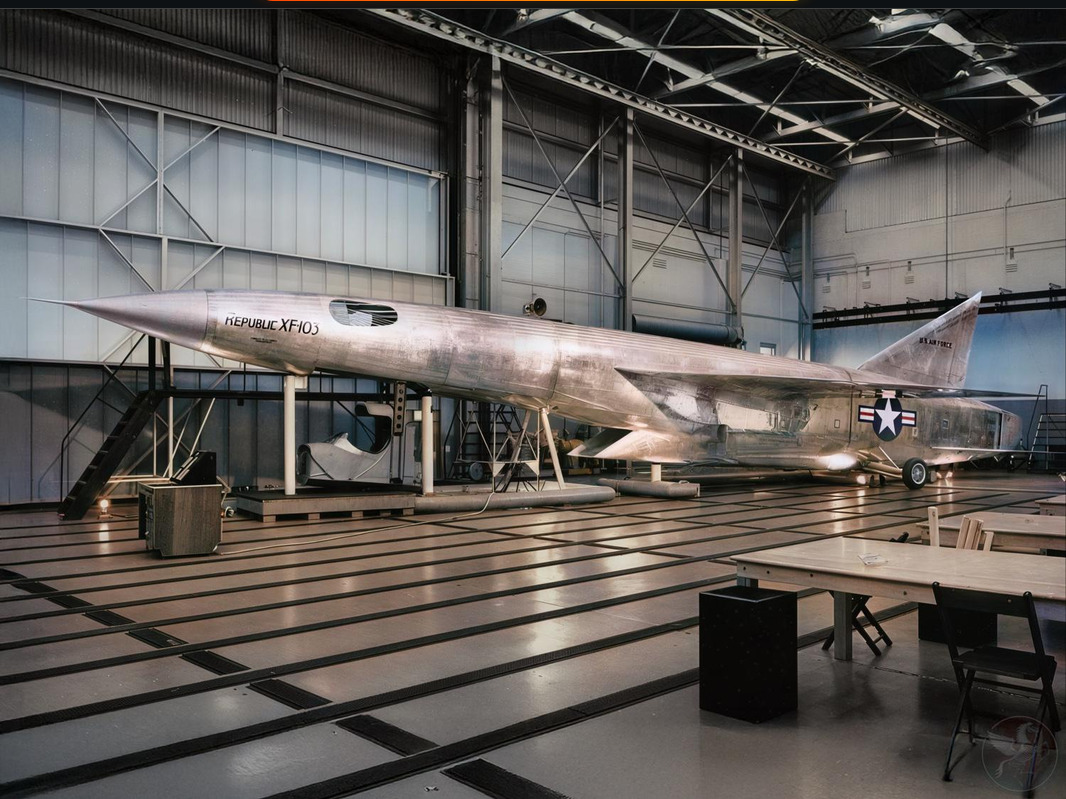
A full-scale metal mockup was inspected on 2 March 1953, impressing USAF officials enough to justify an additional eighteen-month Phase I extension for continued work on titanium fabrication, high-temperature hydraulics, escape capsules, and periscopic sights.
The original XF-103 forward fuselage mockups showing the raised cockpit (right) and flush design (left) mounted on large wooden braces at the exact height the aircraft would be above the ground. (Frank Strnad Collection via Helen Strnad)
Originally, Kartveli designed the XF-103 with a conventional canopy and windscreen. However, concerns about aerodynamic drag and the thermal limitations of plexiglass at sustained Mach 3 speeds led to a complete redesign of the cockpit.
Final XF-103 configuration showing flush cockpit design. (Republic via Charles E. Rogers)
The revised cockpit sat flush with the fuselage. Two large side windows provided adequate visibility during takeoff and landing, while a retractable periscope supplied forward vision at high speed. Target tracking during combat would primarily rely on the MX-1179 radar display, although an optical sight was also included.
These drawings provide a good look at the overall interior configuration of the final XF-103 design. (Republic via Charles E. Rogers)
To validate the cockpit concept, Republic built a full-scale cockpit section and mounted it on a truck adjusted to simulate the XF-103’s seating position. The vehicle was driven around Republic’s facilities at Farmingdale, New York, while engineers photographed visibility through both the periscope and side windows. Simultaneously, comparison photographs were taken from an F-84G equipped with an A-1 gunsight.
This was the field-of-view from the XF-103 cockpit as seen from a full-scale cockpit placed atop a truck and driven around the airfield at Farmingdale. (National Records Center, St. Louis)
Testing showed that the XF-103’s periscope actually provided slightly better forward visibility than the F-84 because there were no windscreen frames obstructing the pilot’s view. Side visibility was excellent, although rearward visibility remained almost nonexistent. Overall, the revised cockpit configuration was judged satisfactory and validated.
Republic ground crew poses with F-84G Thunderjet serving as an inflight Proof-of-Concept test bed, fitted with a periscopic sight to be used on the XF-103.
The pilot was to sit inside a fully enclosed escape capsule. Before flight, the capsule would be lowered to ground level along rails so the pilot could board. During an emergency ejection, a sliding door would move upward between the pilot and the instrument panel, sealing the capsule completely. Interestingly, the flight controls and throttle were mounted inside the capsule itself and were to be mechanically connected to the aircraft when locked into position.
Actual XF-103 escape capsule designed and built for drop tests to confirm its operational safety performance parameters. Stabilizing fins are shown in their deployed positions above and aft of the capsule, and would be folded above and behind the capsule’s main body while inflight. (Via Helen Strnad)
A complete XF-103 escape capsule was built by Coleman Aerospace for Republic Aircraft and tested during an airdrop from a B-47. Although the parachute failed because it was undersized for the aerodynamic loads, the capsule itself survived the impact on the Edwards AFB bombing range with no major structural damage.
Setback and Termination
The XF-103 was among the first aircraft programs to extensively investigate titanium construction, paving the way for later aircraft such as the Lockheed Blackbird family and the North American XB-70. Republic evaluated four different structural construction methods and concluded that an all-titanium structure offered the lowest weight, while a mixed titanium-and-steel structure ranked second.
Development proceeded slowly as Wright struggled with developing the J67 engine. Although contracts for landing gear and titanium tooling for three prototypes were awarded and expected first flight as early as February 1957, it gradually became apparent that the XF-103 would never fly.
Nevertheless, the Air Force still desired an interceptor capable of outperforming the forthcoming Ultimate Interceptor. Consequently, on 6 October 1955, it issued GOR-114 for the Long Range Interceptor Experimental (LRI-X) program, seeking a new Mach 3 aircraft.
Anticipating the LRI-X, the XF-103 program was reduced in early 1957 to a single prototype and two flight engines. Rather than becoming an operational interceptor, it was intended to serve as a high-speed research aircraft for future Mach 3 interceptor development of the LRI-X program.
Rare photograph of the XF-103 rocket sled at the Hurricane mesa Supersonic Test Track. Note the forward fuselage is mounted on the sled base inverted, so the downward escape capsule could be tested and fired upward from the rocket sled track. (Via WINGS & AIRPOWER Magazine Archives)
Little additional progress was made, however, and both the XF-103 program and the Wright engine were officially canceled on 21 August 1957. Over its nine-year development, the program cost approximately $104 million. Although the aircraft never progressed beyond the mockup stage, it produced valuable research and engineering experience that benefited later high-speed aircraft development.
A render of XF-103 in its final configuration.