part 2
For a full Hellfire loadout an external stores rack was installed which could hold eight additional Hellfires. Or, additional stingers could be carried.
The external rack was also used for two range extension tanks for self-deployment ferry missions up to 1260 nm range.
The Comanche was designed for air transportability in a number of Air Force transports. It met or exceeded the entire required load and unload timelines.
Supportability was a high priority for the Army to reduce operations and support costs and to improve aircraft availability in the field. Comanche’s unique fuselage design permitted judicious locations for doors and access panels, easing the maintainer’s job. Two maintenance levels were planned compared to three for the existing fleet. A 40% reduction in maintenance burden was projected compared to the existing fleet.
The following describes the Comanche at the time of the Full Scale Development proposal, August 31, 1990. Some of this was altered as the program proceeded.
The Fuselage
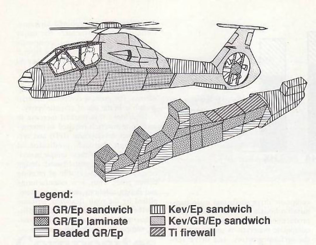
After many conceptual design studies, the Boeing Sikorsky team chose an unusual design for the fuselage. Unlike virtually all other helicopters (and fixed wing aircraft for that matter) it was decided not to use the exterior surfaces of the aircraft for the primary fuselage structure. Because of the need for a low radar signature, the aircraft weapons had to be stored within the fuselage and then extended out when they were to be deployed. LHX also required a retractable landing gear for both low radar signature and for high speed. Additionally, the Army’s emphasis on supportability required many access panels to simplify maintenance tasks. It became apparent that a conventional fuselage would be very structural inefficient (i.e. heavy and flexible) and difficult to design. An alternate approach was created to have a simple structural box beam internal structure with the outside skin unloaded from the primary structural loads. Doors and access panels could then be placed in the most optimum positions, improving both radar signature and ease of maintenance for the internal components.
Early in the program this started to be described as the “fuselage within a fuselage” with some derogatory implications that it must be too heavy. In actuality, it became one of the most positive attributes of the Boeing Sikorsky design.

Bruce Kay, Sikorsky Chief of Design, with fuselage skin display
Use of advanced materials in the fuselage
The Main Rotor System
Advances in technology lead to a new concept for the main rotor, the bearingless main rotor, or BMR. This was a simple flexbeam which replaced the conventional flapping, lead-lag, and pitch change bearings of existing helicopters. Early helicopters had metal bearings for all three motions and these were grease lubricated. This then lead to oil lubricated bearings to reduce maintenance requirements. In the 1960s a concept was developed to replace these conventional bearings with elastomeric bearings that require no lubrication; first being used on the Sikorsky CH-53D and then on the UTTAS/Black Hawk.
The Black Hawk tail rotor was the first production use by Sikorsky of the flexbeam concept. It used two graphite flexbeams connecting two rotor blades, clamped together for the four-bladed rotor. The LHX applied the flexbeam approach to the main rotor.
The Pentaflex rotor
Conventional hinged rotors have a specific hinge offset – the ratio of the flapping hinge position radially as a percentage of the rotor radius. This strongly affects the rotor control power and dynamic characteristics. Helicopters then in production had hinge offsets from 0 to 5 percent. Bearingless rotors have the same attribute, using the term “equivalent offset” to compare them to hinged rotors. Because LHX was to be a very maneuverable aircraft, a high equivalent hinge offset was desired. Boeing Sikorsky chose a 10% equivalent offset to get the agility desired for LHX.
A decision was made to use five rotor blades to reduce individual blade forces and moments as well as to improve the rotor’s acoustic signature. Thus the rotor was called a “Pentaflex”. Variable speed was also used to help control the acoustic signature. This was accomplished by varying the engine speed.
The rotor had a diameter of 39 ft. Blade chord was 15 inches. Twist was -11.1˚, or -13.5˚ on a thrust weighted basis. The blade out to 85% radius used a Boeing 10% thick VR-12 airfoil. This transitioned by 90% radius to a Sikorsky 9% thick SSC-A09 airfoil. The outer 8 percent of the blade was swept and tapered. The SSC-A09 airfoil for the tip was chosen because it had a high maximum lift coefficient and a high drag divergence Mach number.
The main rotor blades were all composite, based on proven low-risk Boeing production designs. They had also been proven to be ballistically tolerant to 23 mm rounds.
Crew Station
Comanche had a two-person tandem cockpit. They were identical and the aircraft was fully operable by one pilot from either station. The flight controls were fly-by-wire with a right sidearm controller for pitch, roll, and yaw control. A left side collective pitch controller was used. Pilots had a 30˚ by 60˚ field of view NVPS (Night Vision Pilotage System) and a dual independent IITV (Image Intensified TV) system. Helmet-mounted displays provided all data and displays for eyes-out flying and fighting with a 35˚x 60˚ field of view. Seats were armored and crashworthy.
Mission Equipment
The Mission Equipment Package (MEP) for Comanche consisted of:
- A Night Vision Pilotage System (NVPS)
- A Target Acquisition and Designation System (TADS)
- A Helmet Integrated Display and Sighting System (HIDSS) in each cockpit
- An Integrated Communications, Navigation and Identification Avionics (ICNIA) Suite
- Four head-down LCD Multi Purpose Displays in each cockpit station
- A Terrain Mapping and Display system
- Plus dual mission computers and systems to make all this functional

MEP performance compared to the AH-64 in 1991
Night Vision Pilotage System, NVPS
The “see” part of “see without being seen” came from the Target Acquisition System (TAS) and the Night Vision Pilotage System (NVPS). These were mounted on the nose of the aircraft to provide maximum field of view, a view unobstructed by the rotor, and to reserve the mast-mounted position for future inclusion of the Longbow system. They included both a Forward Looking InfraRed system (FLIR) and a Low Light Level TV (LLLTV). The NVPS provided both navigation and reconnaissance capabilities, was capable of night nap-of-the-earth and terrain avoidance flying in adverse weather conditions, and gave a clearer definition of the horizon than previous systems.
The FLIR at that time was “second generation” and could detect smaller temperature differences than earlier FLIRs. (The actual temperature numbers are classified.) It also included an image intensifier function. It had a 30º by 60º sensor field of view, and a 35º by 60º field of view as displayed on the pilots’ Helmet Mounted Display (HMD). This was a 31% increase over what was then being used on the AH-64 Apache. The visual range of the system was a 40% increase over the Apache.
Target Acquisition System, TAS
The target acquisition system had the same advanced features as the pilotage system, with a second generation FLIR and a 40% increase in standoff and detection range. Also, it included a heads-up, eyes-out helmet-mounted display, and the ability to work in adverse weather conditions and with battlefield obscurants. It also had an Aided Target Detection and Classification (ATD/C) function with files of known enemy vehicles which could be compared with the view being received. This included a search-on-the-move function; moving target detection; and automatic multitarget prioritization, tracking, weapons selection and fire control. Hover search times were less than six seconds; scene review was conducted after the aircraft had remasked. When a match was found, this information was displayed to the pilots, and a weapons cueing/rangefinding function initiated. This resulted in a 95% reduction in target acquisition time and three times more target location accuracy compared to systems then in use. False alarm rates were projected to be five times lower than the Army’s requirement.
Helmet Mounted Display
The HMD included individual, independent bi-ocular wide-field-of-view displays with image intensifiers. Symbology for heads-up and eyes-out operation was included. The imagery consisted of sensor video from the Night Vision Pilotage System (NVPS) or the Electro-Optic Target Acquisition and Designation System (EOTADS) and video from the helmet mounted image intensifier sensor. Symbology consisted of flight graphics and alphanumerics which were overlaid over the imagery.
Integrated, Communication, Navigation, and Identification Avionics, ICNIA
The Integrated Communication/Navigation/Identification system included Global Positioning (GPS) navigation with accurate back-up provided by both Doppler and inertial inputs to assure mission completion. The navigation system was fully coupled to the flight control system to provide automatic flight along selected waypoints. Navigation and tactical overlays were provided on a digital map for tactical awareness and easier, more thorough mission planning. Optimum route selection was updated in real time. Target data could be transferred from the aircraft to the tactical operation center. The system was designed to be highly fault tolerant, reliable and survivable. It was designed for straightforward future growth.
Mission Electronics
The mission electronics used highly redundant, fault-tolerant architecture. They included 33-bit processors, an 800-Mbps sensor bus, a 50-Mbps data bus and dual 1553 data buses. It was projected to have a 95% level of automatic fault detection and a 98% level of automatic fault isolation to the line replaceable unit (LRU) level. Electronic racks were installed in the rear of the fuselage at waist-high level where they were easy to access for maintenance. Compartments on both sides of the aircraft provided separation for improved survivability. Racks were sealed and cooled with filtered air. They were pressurized for moisture- and NBC-protection. The design included 30% spare processor capability and a 50% bus throughput margin in reserve. 14 open rack positions were included for new modules and capabilities, such as the LONGBOW preplanned product improvement. Modular electronics is located in the tailcone for ease of maintenance and growth
They also included embedded programs for in-cockpit training of the various systems.
there is more but i don’t want to spam i just hope this give more info about the Rah-66 !