text from post 1
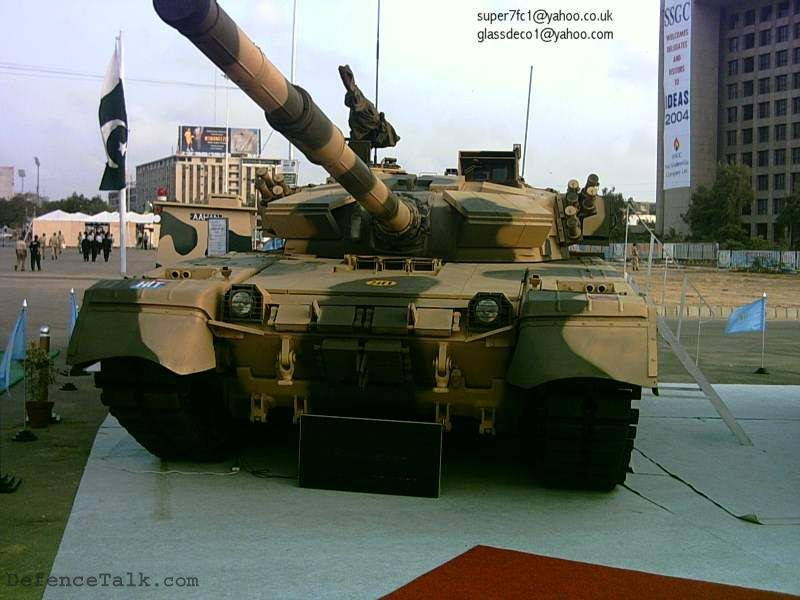
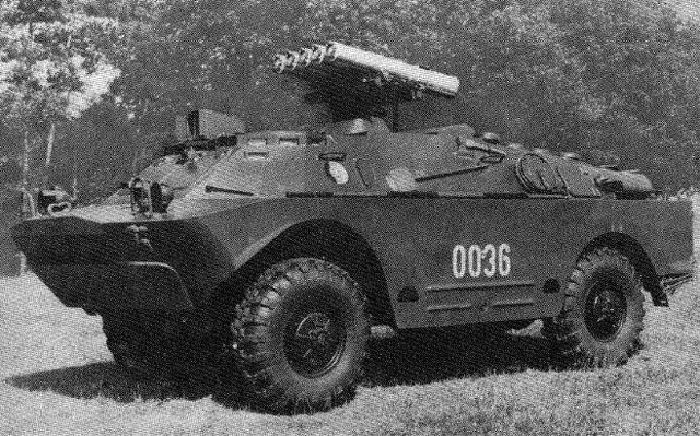
Today we will talk about completely perverted German fantasies, namely about the VT1-1 and VT1-2 tanks, or as they were also called “Leopard 3” (not to be confused with the future MBT). It was in the early 70s, with the MBT-70 project things somehow did not work out right away, they did not share the gun, engine and other units. But a new main battle tank was still needed. And it was very necessary, since tankers somehow did not particularly show a desire to fight on spotted cats 1 against the new-fangled Soviet T-64. All Western military personnel were shocked by the sixty-fours.
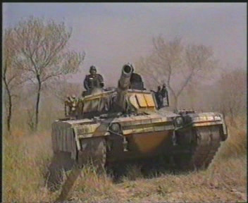
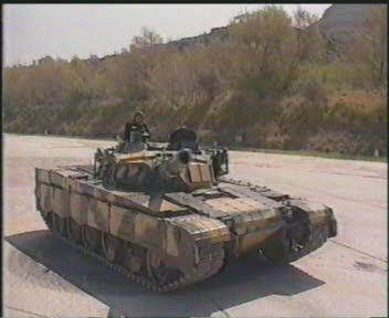
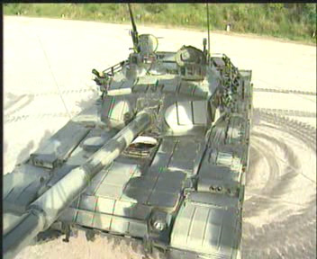
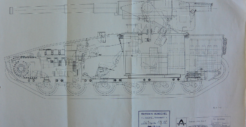
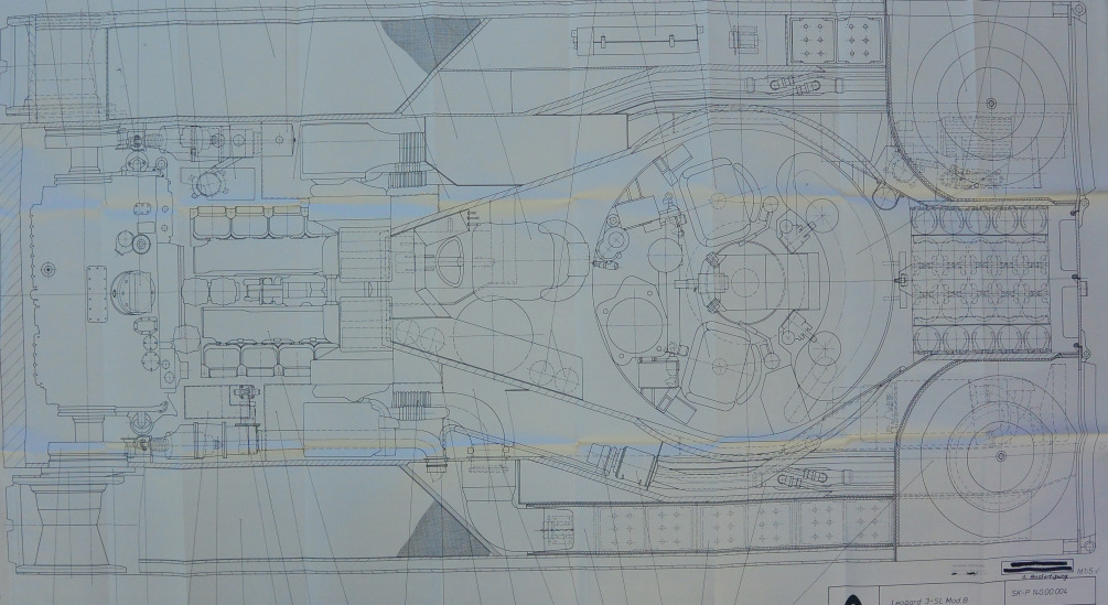
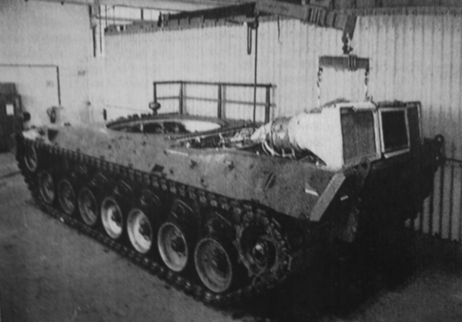
As a result, the Germans continued working on a new tank with a standard layout. But there were some particularly clever ones, like engineer Wolfgang Matos, who headed his own project for a new tank. He considered the standard layout to be obsolete and did not particularly believe in the prospects of the Leopard being developed in a neighboring project. As a result, they developed a new tank with a turretless layout. And apparently they thought then that one gun is good, but two are better. Therefore, they stuffed two guns into both prototypes, on the left and right sides of the vehicle. The guns were aimed vertically using a drive, and horizontally by turning the hull. At a range of 1.5 km, the axes of the guns intersected.
The first prototype VT1-1 was equipped with two well-known English L7 guns. Each gun was equipped with an automatic loading system, a trend of the time, and still cool today. The second prototype VT1-2 was even more terrifying: it carried two 120mm Rh 120 guns, one with automatic loading, the second with manual, because the gloomy genius was unable to make a mirror copy of the AZ. Both vehicles were equipped with a PERI R12 sight, which was borrowed from a neighboring project. When firing while standing, the vehicle showed better results compared to turret tanks. But firing on the move became a problem, although this was clear even at the sketch stage. The tank could not aim normally on the move in the horizontal plane, when firing, the vehicle rocked and skidded strongly, the trajectory of movement changed, it was difficult for the driver to control the equipment in such conditions.
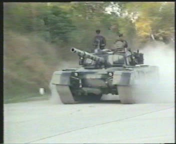
In terms of mobility, everything was fine. The vehicles inherited the chassis from the KPz-70 with hydropneumatic suspension, but the hull was shortened and one support roller was removed. A 1,500-horsepower engine was used as a power plant, yes, again taken from a neighboring project. The engine was initially boosted to 2,000 hp and installed on the VT1-1. And on the VT1-2 it was boosted even more, reaching a power of 2,200 hp. The mass of the vehicle was 38-40 tons, which, combined with such powerful engines, gave an incredible 53 hp/t. Modern MBTs, and what’s more, even light tanks smoke on the sidelines. Therefore, the vehicle was very mobile.
The crew consisted of 3 people: commander, gunner and driver. The driver was located in the center at the front of the hull. Behind him were the commander and gunner, to the left of the tank’s axis. The armor was not seriously considered, the Germans still believed that “barnya nenadka!” and relied on firepower and mobility, let me remind you, 2 guns with an automatic loader and 53 horses per ton. Experimental models were made of regular steel, not armored steel, which saved weight. A real tank would have weighed 2-4 tons more. After a lull, in the 80s the project was revisited and several more GVT prototypes were made, on which the guns were moved closer to the center and the internal layout was changed, on some variants the chassis was lengthened.
From 1972 to 1976, the VT1 underwent a test cycle. During this time, they drove many kilometers, fired a lot of shots, etc. As a result, it was impossible to shoot normally on the move, the layout was strange, the neighboring project showed good results. Later, the spotted cat two was born, and the military came to the conclusion that why the hell do we need this, it is better to modernize the Leopard 2. Therefore, the Leopard 3 project was abandoned. In the 80s, they returned to the project again, tested the GVT and eventually closed the project completely and decided to improve the Leopard 2, and thank God. But the double-barreled tank was developed as a promising replacement for the Leopard 2.
text from post 2
Experimental two-gun tank VT1
In the early 1970s, the MaK (Maschinenbau Kiel) company began to consider the prospects of modern tanks on its own initiative. It was assumed that the vehicle being developed, designated VT1 (German: Versuchstrager 1 - test model), would be ready by the time its “peer” Leopard 2 began to become obsolete.
During the analysis of the existing designs, MaK analysts and engineers came to the conclusion that the existing tank layout with a rotating turret and only one gun was no longer capable of providing the necessary firepower. In addition, the success of the Swedish turretless Strv 103 tank, which managed to combine sufficient firepower (105-mm gun) with good performance, maneuverability and protection, had an effect.
True, the rigid fastening of the gun required a significantly more complicated suspension: vertical aiming was carried out by skewing the entire hull. German engineers decided to adopt the idea of a tank without a turret, but at the same time not to be clever with the aiming of the gun. At the same time, a group of engineers led by Wolfgang Matos came to the conclusion that it was necessary to install two guns on the prospective tank at once. According to the designers, it was not possible to achieve a significant increase in combat qualities by other means.
The experimental MBT-70 tank was chosen as the basis for the new experimental design. This armored vehicle was not suitable for serial production, but was attractive for use in experimental work on the VT1 topic. In accordance with the turretless layout of the future tank, the chassis was shortened, due to which instead of six road wheels per side there were only five.
The hydropneumatic suspension was modified accordingly. The MBT-70 tank’s native Continental AVCR-1100-3 diesel engine was replaced by an MB 873 Ra-500 diesel engine. The new engine could operate continuously, producing one and a half thousand horsepower, and “accelerate” to 2175 hp in a short time.
At the same time, in emergency mode, the 38-ton tank had a specific power of over 50 hp per ton of weight. This is approximately twice as high as most modern tanks. One of the reasons for the high specific power was the comparatively low weight of the structure. Given the experimental nature of the project, MaK engineers made experimental tanks not from special armor steel, but from lighter “regular” grades. In this way, about 2-4 tons of weight were saved. An armored cabin was installed on the modified chassis of the MBT-70 tank. It is noteworthy that with a comparatively large internal volume, it did not have very large dimensions. The overall height of the VT1 was slightly more than two meters, which was more than 80 centimeters less than the original MBT-70.
In 1972, the assembly of the first prototypes of the VT1-1 tank was completed. The first example was equipped with two 105-mm rifled L7 guns. Both guns had automatic loaders.
The VT1-2 tank, in turn, received 120-mm smoothbore Rh-120 guns. However, only one gun was equipped with an automatic loader. The fact is that during the development of the new tank, the designers of Maschinenbau Kiel were unable to produce a mirror version of this unit. Therefore, one gun was loaded automatically, and the second was fed shells and cartridges by the crew manually. The design of the gun mounts on the VT1-1 and VT1-2 tanks is interesting. On both vehicles, the guns had the ability to only aim vertically. The guns did not move horizontally. In addition, they were installed with a small convergence angle: the aiming lines intersected at a distance of 1,500 meters.
Testing of the two prototypes continued until 1976. During this time, the tanks traveled thousands of kilometers across the testing ground and fired hundreds of shots. First of all, it became clear that the VT1-1, due to its very concept, was not capable of firing more or less accurately on the move. When firing from one gun, the recoil slightly turned the tank around the vertical axis, which had to be countered by turning the entire tank. This problem was only aggravated by the lack of sighting devices for the driver.
Only the commander and gunner had Carl Zeiss PERI R12 periscope sights. Naturally, in combination with the lack of horizontal aiming of the guns, this greatly complicated firing. In addition, the design strength limitations did not allow both guns to be fired simultaneously. Thus, the only way to somehow eliminate the tank turning during firing was “prohibited” by the design itself. It is noteworthy that on the above-mentioned Swedish Strv 103 tank, aiming was carried out by the driver. For this purpose, he had a sight and controls for the hull tilt.


