Hello,
@Smin1080p_WT
I am tagging you here because at this moment in time, I cannot bug report this issue due to requiring further information from the moderators regarding what data I can and cannot use (I am currently using datamined code).
As such, I heavily request a response asap.
TLDR: DIRLCM is (incorrectly) modelled as static FOV DIRCM, not as a turreted system
And I challenge the devs to explain their implementation to me if i get it wrong
.
.
.
For detailed explanation, read on
What is the issue?
I have been scanning the games code, and more importantly, the .blk files that comprise of the majority of vehicles, sensors, and other relevant systems in War Thunder. What I have found is the following:
There is a completely wrong implementation of the DIRLCM system when compared to an already present system (in terms of turreted DIRCM) in game.
My example:
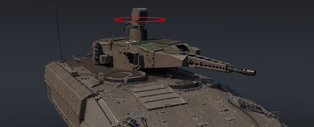
Puma IFV
The Puma IFV has a DIRCM system called MUSS. It is a softkill active protection system. IRCM, DIRCM and DIRLCM systems are all softkill active protection systems.
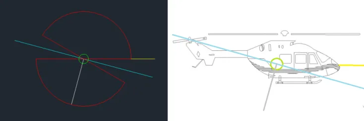
What makes MUSS special is that it can orient itself into the direction of the incoming threat, thereby affecting the incoming missile. (Traverse shown in red)
Here is the code in the germ_schutzenpanzer_puma.blk:
-
Countermeasure block
-
Active protection system block
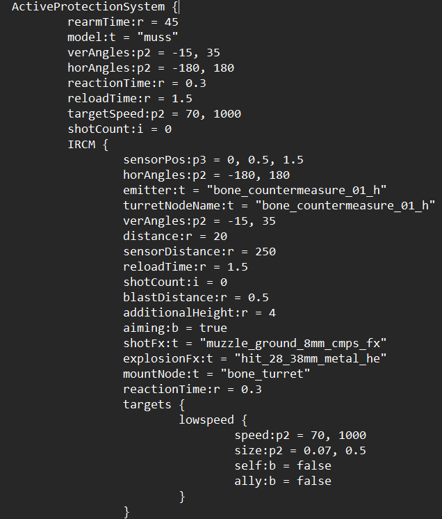
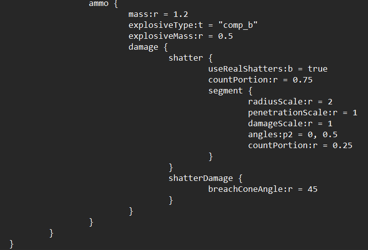
It is important to note, that while the Active protection system block has an “ammo” sub block, this does not work in game, and it should not, since MUSS is purely softkill.
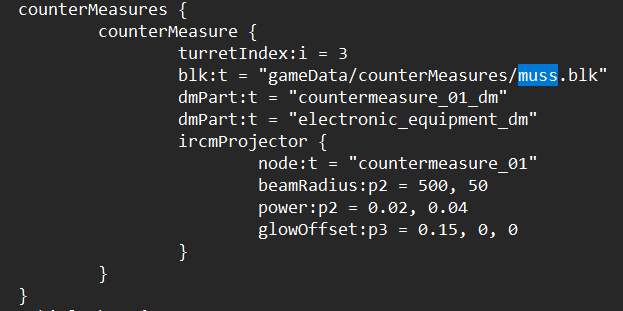
Here is the code in the muss.blk:
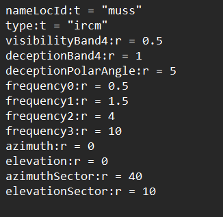
Analysis:
MUSS DIRCM on the Puma IFV (and Puma VJTF) is (correctly) modelled with a turret, of which, the horizontal rotation limits are modelled in the active protection system block as:
verAngles:p2 = -15, 35
horAngles:p2 = -180, 180
These values are repeated in the IRCM subblock:
horAngles:p2 = -180, 180
verAngles:p2 = -15, 35
These limits define the absolute traverse and elevation limits of the DIRCM emitter.
Lets look at the US DIRLCM system:
In ah_64e.blk there is a block called: counterMeasures
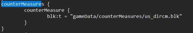
this gives us the name of the (laser) DIRCM system, being “us_dircm.blk”.
Here is the code for it:
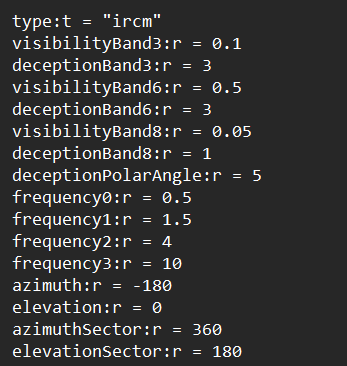
What is different between the muss and us_dircm (aside from one being laser based)?
While the DIRCM emitter for MUSS has limited FOV
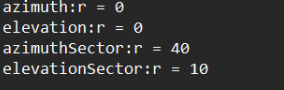
Its TURRET (in active protection system block) is what allows it to cover 360 degrees in horizontal around the vehicle.
![]()
This means that the MUSS has a 40degree wide, 10 degree tall DIRCM cone of effect, which it can direct in the direction of the threat using its automatic turret. This is logically accurate since a DIRCM beam cannot be facing in a direction that the emitter is not facing.
However, the us_dircm is modelled like a static DIRCM with a laser band and 360 degrees of azimuth and 180 degree elevation. What this does is it makes a half sphere of CONSTANT effect which can decoy an infinite number of missiles. The keep eyed of you will notice, MUSS has a reaction time of 0.3 seconds.
But us_dircm does not have anything of the sort. This further goes to show that DIRLCM systems are currently modelled as static sources of IRCM with an area of effect unrealistically wide. the FOV and total traverse limits are being incorrectly modelled the same.
What is the solution?
Its simple, give all LDIRCM helicopters an active protection system block just like the Puma and Puma VJTF have, decrease their FOV (since a laser beam has a very small FOV often 1 degree as compared to currently, it is 360 degrees in azimuth and 180 in elevation).
I await the response from Smin AND want to know how i can go about making a report for this.
In the meanwhile, i will be attempting to create a custom blk file for an Mi-28NM/AH-64E/Z-10ME that implements this turreted DIRLCM.
If i can do it, so can the devs.
Regards.