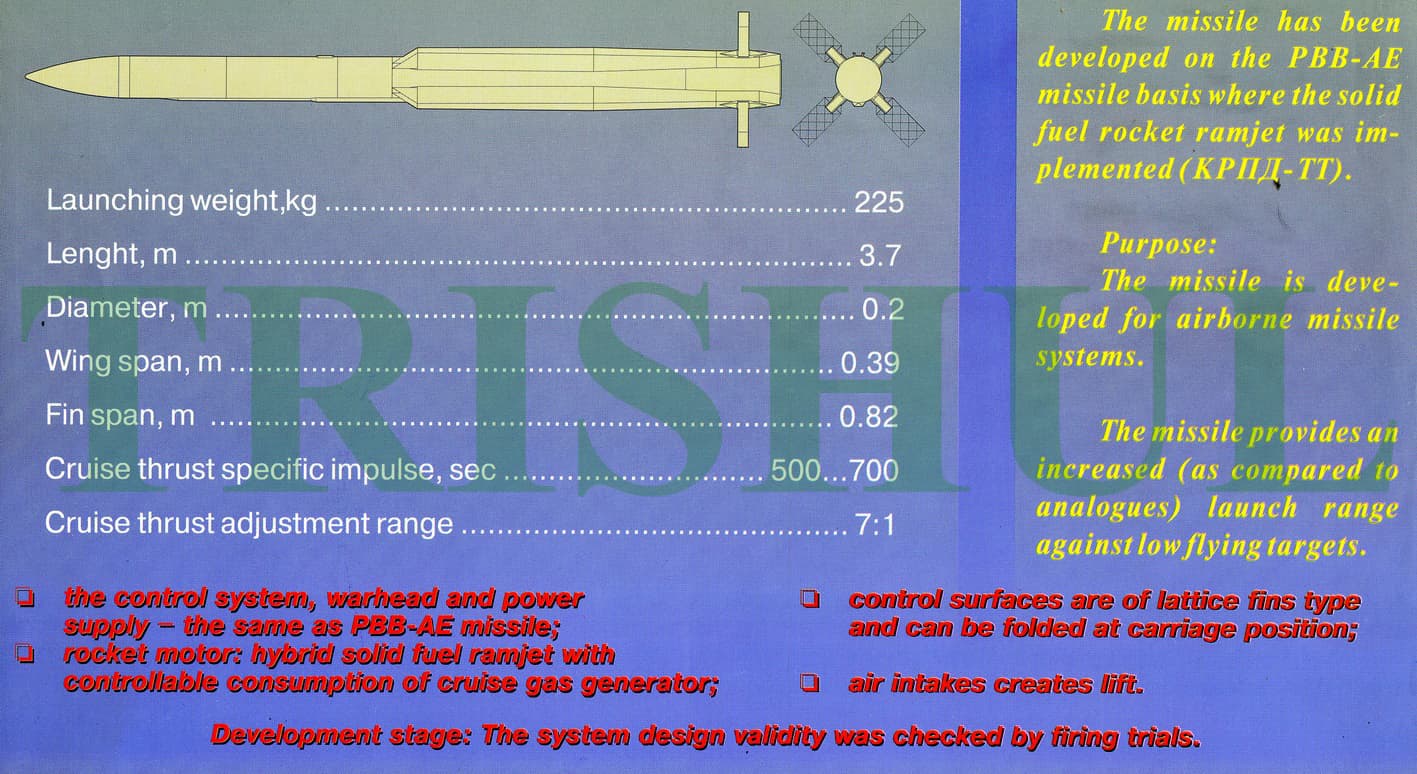
Ground tests only
1 Like
Somehow studied this photo…
Personally, it seems to me that the new rocket is closer in scheme to the famous 3M9…
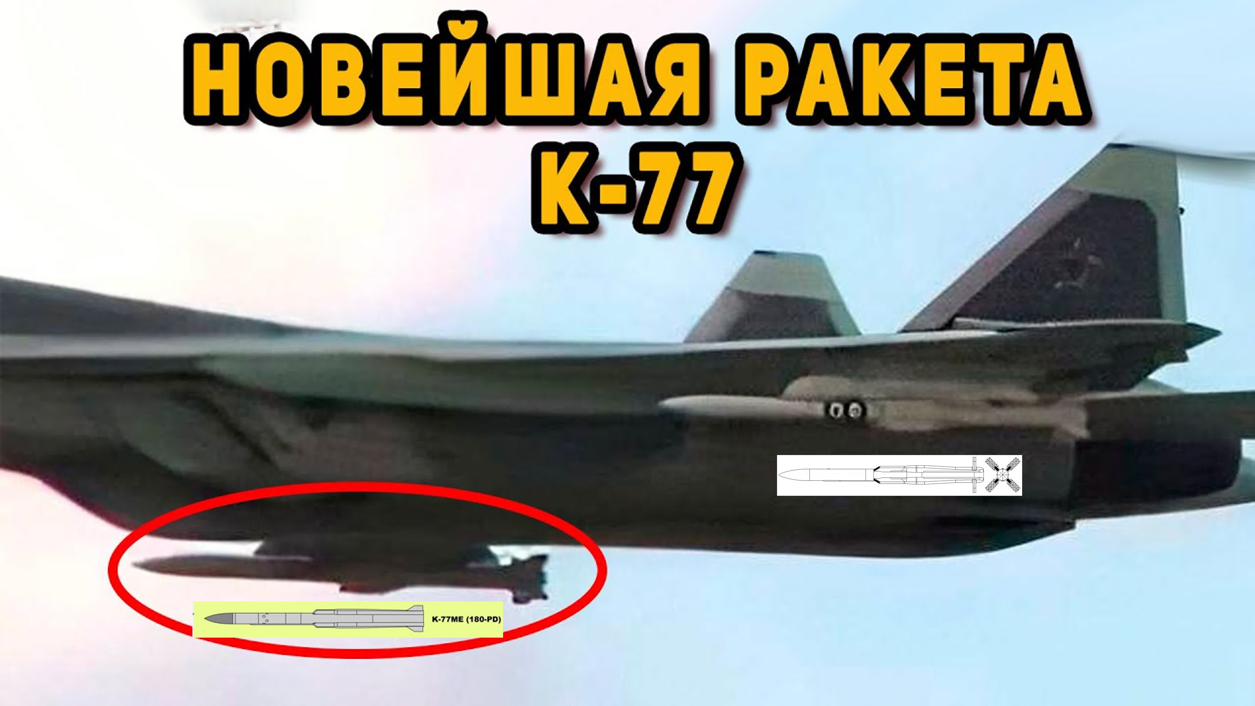
It is just motion blur distortion
Just to ask a question for confirmation, R-77-1 uses 9B1103M seeker whilst R-77 uses 9B1348 seeker, is that correct?
That is also the one proposed for R-27EA/EM right?
and then the 350 mm version for R37.
Edit NVM not the R37. That’s for 9M38.
That page said so. Note that 9b-1103M its old. and 9b-1103m-200pa its more modern.
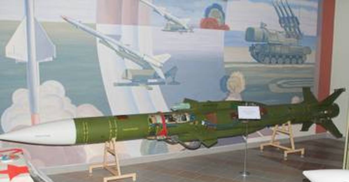
R-27EA - with multifunctional monopulse Doppler active radar SNS 9B-1103M (see description). Range of fire at ZPS is 130km, at PPS - 60km.
edit; yea page said 9B-1103M-350 homing head | Rocketry its for 350mm
thread necroing!
Aight, so… i need help, does anyone know how to do some proper CFD analysis and/or have access to a proper CFD software? i’m making an R-77 CAD model for the purposes os finding out just how draggy or not draggy it is.
DISCLAIMERS:
i am NOT a CAD designer by trade nor an engineer, therefore the model is not gonna be a perfect 1:1 of the R-77, the main areas that are wrong and may or may be wrong are:
The nose cone geometry
The wings size, shape and placement
The grid fin mountings are entirely different as i do not have the skills to recreate the ones on the real missile. They may also difer in placement
The rear body of the missile.
with this out of the way, here are some screenshots of the model


if anyone can help i’d appreciate it a lot, thx
1 Like

Base R-77 Have these “protrusions” at the base of the fins

R-77-1 Have less of these protrusions
Problem with finding out the drag is that you would have to find the width of the grid fins each lattice. They form wedge with small angles, that would have to be modelled too, which is pretty hard to do from just images, but they indeed taper, which you mislooked, it may effect the simulation significantly
Other than this, it would be better to have it as comparision to aim120a/b and c5.
Also, the missile rail is not modelled
![]()
the geometry for the R-77 fins is known: 200mm long for 100 wide and 35mm thick with .75mm thick sheets (that is as modelled)
can easily change that so they are more streamlined than just blunt
yeah, i don’t got the skills for that, that’s why the fin mounts are different too
1 Like
nice, have them tapered tho, like wedge


they don’t taper, it’s just the orthographic view (perpetual 2d) that can throw off a little if you’re not used to it (i’m still getting used to it)
one big issue i don’t know is wether or not the leading edge of the lattice is blunt like this or not

(edit: are we talking about the same thing in different ways? : | )
by tapered i meant they are sharp, like wedge, not blunt

aye, my bad, i’ll edit it!
2 Likes
also as i said before, better make a amraam model as comparision, as the simulation may not give the real IRL values at it might not be calibrated to it, however with results for both missile, we can relatively compare if in game values are accurate or not
amraam should be easier to model

( i suck at modelling, cant make shit, only remember making a nice modular swingy thingy which took me days )
if you can dm me amraam geometry i’ll make a comparaison yes (providing someone is willing to help me with CFD or my ansys stops being iffy)
ill look up on it


1 Like
new fins, thx for pointing it out
Spoiler

1 Like