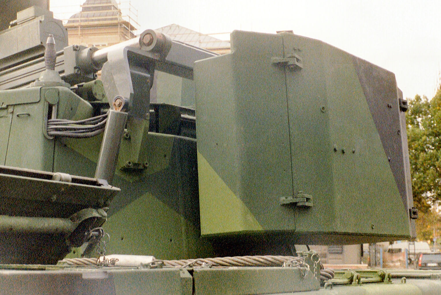
The red highlighted mechanism is the folding hinge. in this “depressed view” is visible compared with the 0 degrees view. is not modelled properly here anyway, but is there.
1 Like
I did not mean to cause any misunderstanding by calling it a prototype, I very much agree with the fact that it was functional, in fact it’s pretty clear that the test program was taken seriously by those working on it, considering how much they edited the 9040A chassis to show how it’d actually be implemented with the basis of their budget in mind. And that there were seemingly plans to test the BILL missiles being added to some 9040s as early as June 2000 due to what I can only guess is some sort of booklet mentioning it.
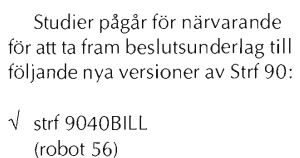
(translation per deepL) Studies are currently underway to develop a basis for decision-making for the following new versions of Strf 90: strf 9040BILL (robot 56)
https://www.aef.se/Resmat/IRMA/IRMA_2000-1.pdf page 14
But unfortunately it only stayed a test product since they both couldn’t afford to put it into production and they couldn’t fix issues with sight alignment.
On another note, I entirely agree about your terrain comment! I had already mentioned this previously as well.
Whilst yes, I’m very much doing that, short of me finding actual documentation on this vehicle as in blueprints or sketches I unfortunately have to. But I will agree with you about what gaijin is doing as you rightly say in the latter half of this quote \/
We as users are made to provide highly accurate and sourced info to even ‘potentially’ have issues fixed (Which is actually a good requirement if the requirements were equal for both parties).
But gaijin has their own internal sourcing that they use to prove otherwise and they aren’t made to show said proof, what they’re using also couldn’t be classified since that’d be illegal (right?) so what’s stopping them from showing us?

I’d have no problem with comments like this for any report, not even specifically for this instance as this could be said for any vehicle in any tech tree, if they gave even surface level proof of their claims.
But even if I personally dislike how they run this part of their game, short of having actual proof that can be provided to say otherwise there is nothing that can be done, as defeatist as that outcome sounds.
4 Likes
The sight alignment is talking about the optics integration with the current systems they had already, in TESTING. This is why they even mentioned that the extra optics were placed on the turret and it was controlled by another person an not the gunner during TESTS.
The intention was to have an integrated system, which is more complicated to do instead of building an integrated system from the scratch for testing purposes
knowing Gaijin they’re gonna turn a blind eye to this post because it’s not a Russian vehicle
5 Likes
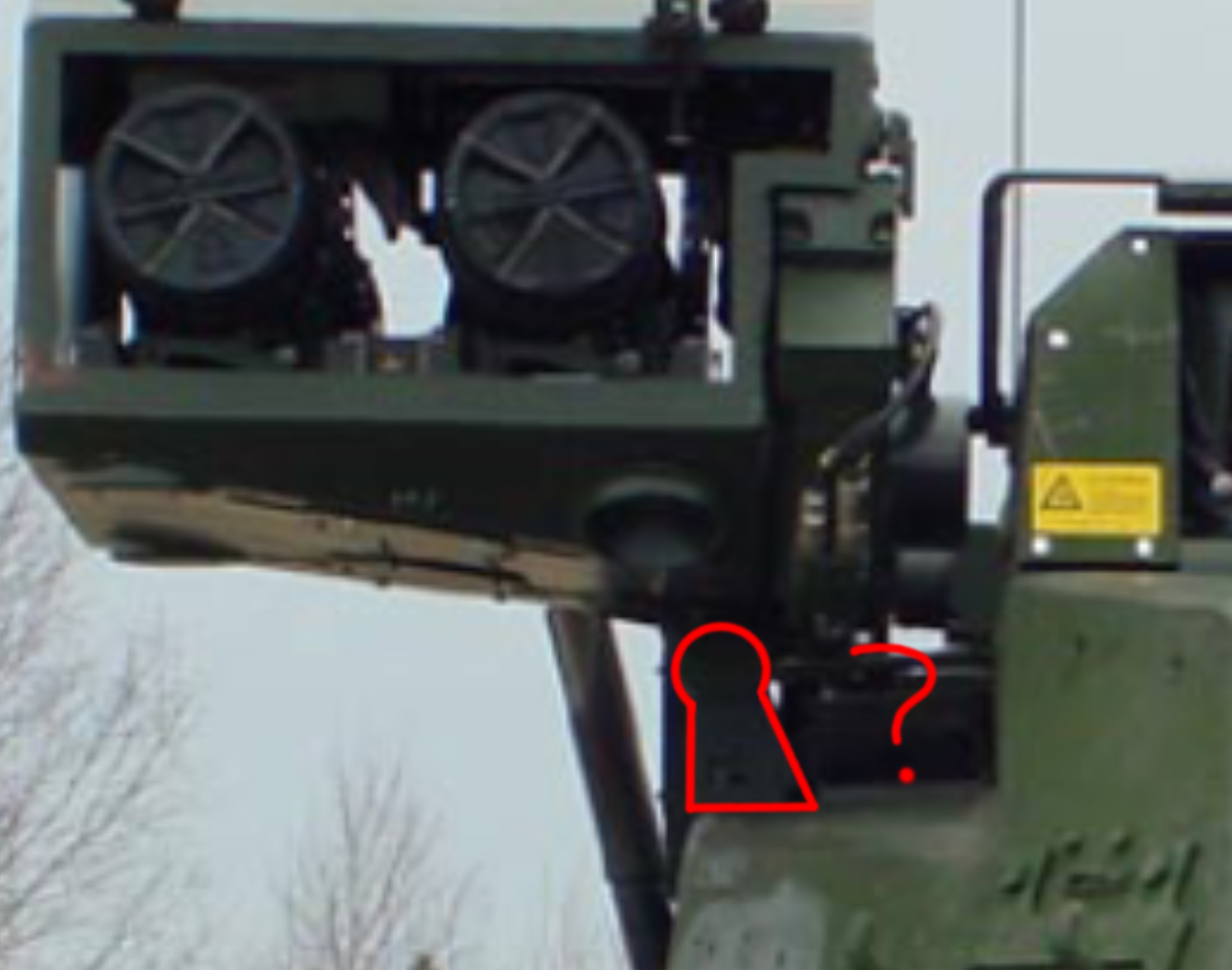
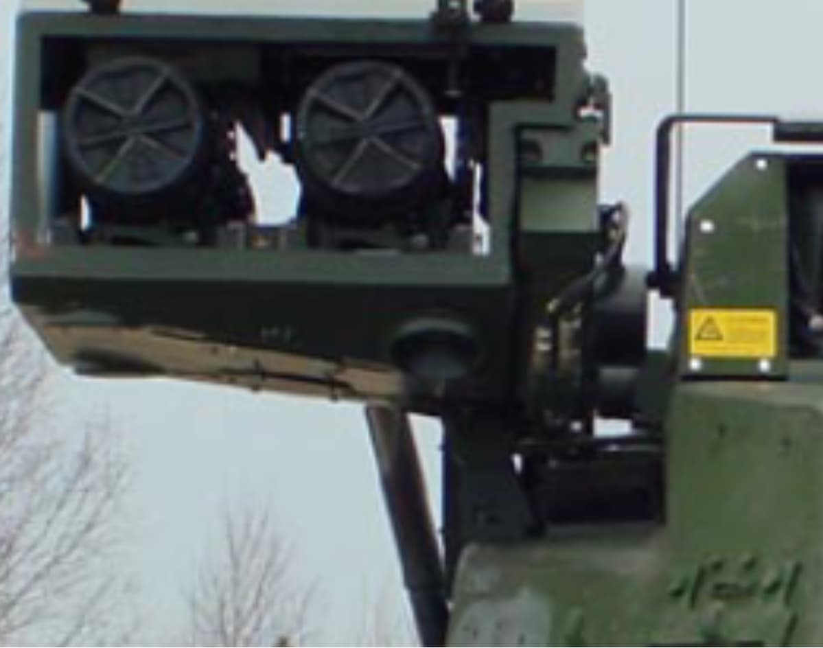
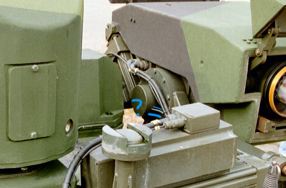
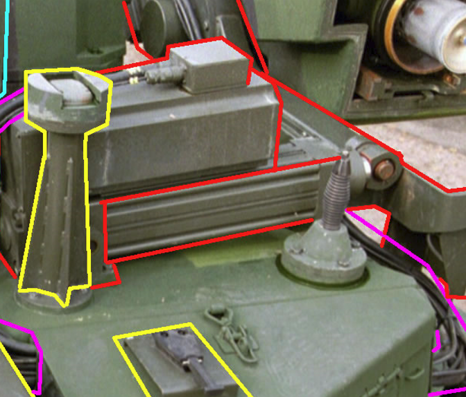
Hi, i have some proof that the “rad” bar doesn’t exist on real Strf 9040 BILL
Also i leave here some photo that i collect and may be it’s can be helpful
CV9040 BILL 2 Photo.rar (9.0 MB)
8 Likes
holy shit those pictures are great. Is it possible to make a bug report with the launcher pictures?
Some picture clearly shows a metal rotational axis, we can finally get the launcher rotation functionality back.
The pictures obviously cannot convince Gaijin. They have many different standards when dealing with different vehicles, and they are quite strict with Bill’s performance. Even with the demonstration video of its firing test, they do not believe it. This is why the problem has existed for almost 3 years, and some vehicles only need theory or imagination without official authoritative information to obtain performance that differs from reality
Photo what i show only confirm that the “rad” bar doesn’t exist on irl prototype.
But i don’t have clear confirmation that the launcher support hinge placed on gunner side is modeled correctly. Also i don’t have same proof abot size of hole in launcher where this hinge placed.
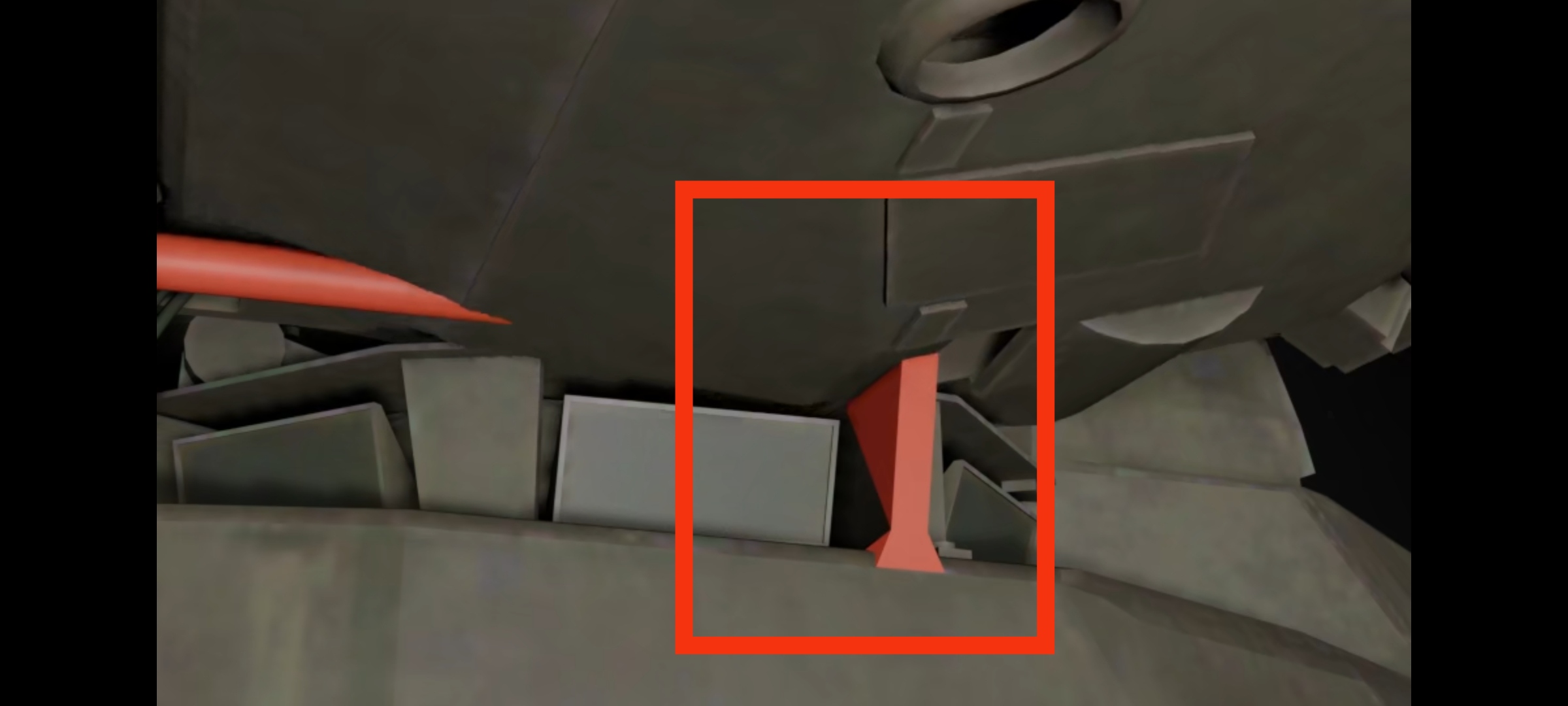
I mean this problem where some parts of launcher clipping when it elevated doesn’t solve by my photo:

I mean there is a wire going into the axis in one of the photos in the rar, which should either power the rotor or control it. Why would there be a wire if not to allow the launcher to move under control?
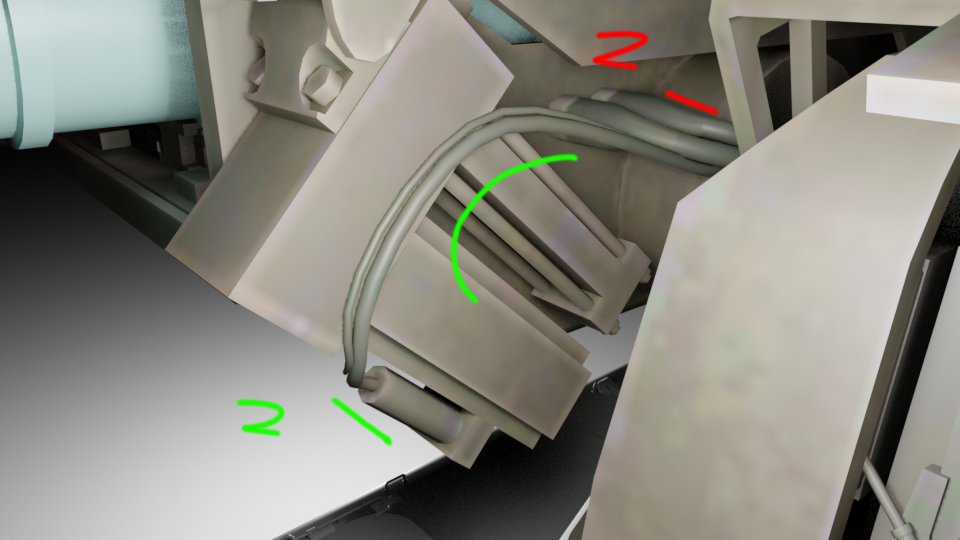
Looked though those amazing images (thank you for those btw) and whilst I do agree that the way that the “red bar” as gaijin has modelled it isn’t present, the front plate that is at the end does seem to exist.

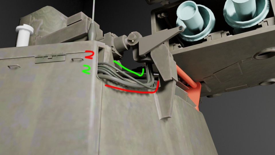
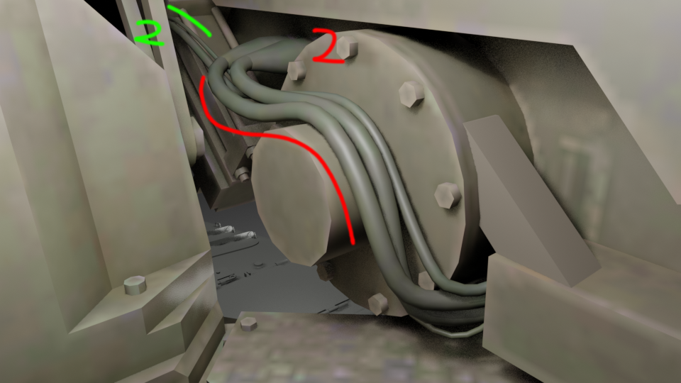
Looking at the images provided by Westland gives me a better idea of the actual launcher and most of the cabling is correct in terms of modelling, however the cables that are correct are very likely for two specific purposes.
- Launching and controlling the missile. (RED)
- Opening and closing the launcher hatches. (GREEN)
(Just ignore the old red bar in the model I forgot to delist it in the image render)
 |
| 
 |
| 
I believe that if those cables I’ve listed as red are used for launching and to provide data for the missile via the tow cable (highly likely).
Then those cables I’ve labelled as green are used to operate the launcher hatches, as those have been modelled to be opened and closed via two arms located on the inside of the launcher that are likely pulled/pushed by another piston located in that front box with the cables (idk how accurate this to irl but it’s how gaijin has modelled it).
Like this \/
|
What I haven’t yet seen till now is a new cable that actually enters that housing that I used to call the “motor housing” back when I thought the launcher could move. (Blue)
^ (Image 15 of 18 in above file if you want to see full uncropped image) ^
This is not shown on the model in game and is entirely new to me, I don’t have any idea about what it could be for other than powering a motor but I could be entirely wrong.
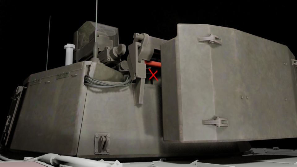
The above image is entirely new to me as the closest image I had to it when doing this originally was covered in blockout lines added by someone else and due to the angle the cable might’ve been barely visible if not for the red outline above the launcher elevating piston mounting \/
6 Likes
I probably should have been a bit more clear with my reply. I meant the blue wire you shown in the pictures. That’s the one that got me excited. Haven’t seen any other pictures showing a wire like that.
1 Like
BUMP - I was looking very closely at the previously-provided video. I am a big fan of CV 90 vehicles and I wanted to take a close look at the BILL launcher on the ingame Strf 9040 BILL.
In this video, skip to 2 minutes 42 seconds and look VERY CLOSE at the launcher’s up/down rotation. Right before the launcher closes its front/rear caps, the launcher goes from being rotates slightly upward to rotating slightly downward to be level, before folding inward.
This is undeniable proof that the launcher can rotate upward, at minimum. Gaijin needs to update the BILL launcher to at least be able to aim up a few degrees according to this live-fire video evidence.
2 Likes
I think an even clearer example is at about 1:57 when it folds the launcher. To me, it seems pretty clear that the launcher is slightly elevated when firing, and depresses to horizontal when it folds down the doors in the front and back.
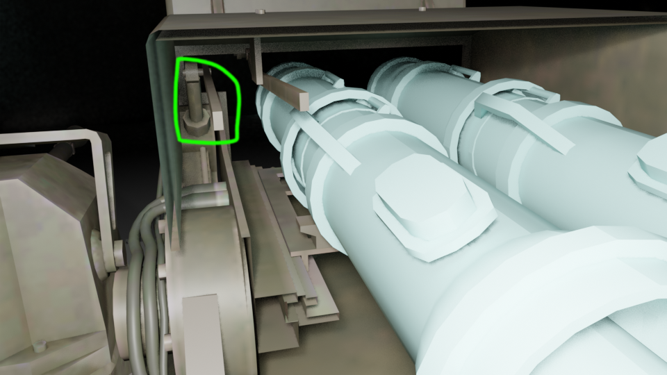
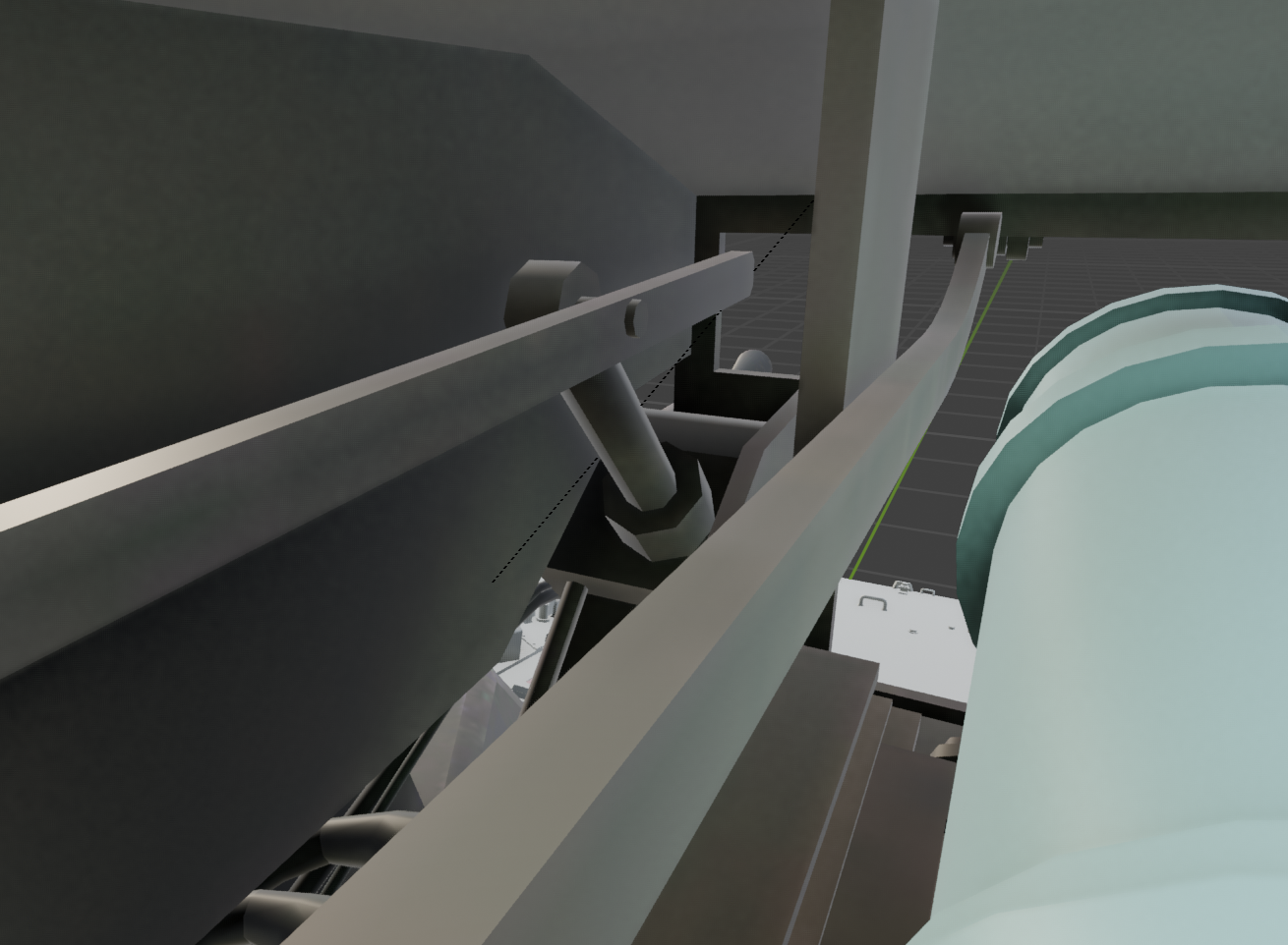
I think the launcher was designed to be able to elevate, but not depress. I believe this because there is a component that looks VERY similar to a linear acutator at the front of the launcher, which is attached to the launcher by a hinge.
This component is just a shorter version of the actuator that controls the folding and unfolding of the launcher. When looking at the component in question, i think it’s clear that the “base”, which is actually a gearbox, is attached to the launcher, and the piston is attached to the mount for the launcher.
N0REAVER previously posted images which shows a angled cutout in the launcher, which would have been required for clearance.
When looking at how they designed the folding mechanism, and looking at how I predict the elevation mechanism works, I think it’s fairly convincing to think that the two mechanisms works almost the exact same way. I can’t think of another function that linear actuator has in that oriantation.
2 Likes
I reported and used this video for argumentation two years ago. The result is obvious: regardless of whether the evidence is reasonable or not, Bill has been clearly forgotten and remains in a damaged state indefinitely
2 Likes
Can you create a new bug report using the latest game version? Let us know and I’ll drop in to +1 it.
I have submitted reports regarding this issue a total of three times, and it was reported long before my reports. Even though there are complete shooting videos of the vehicle on YouTube, they still refuse. They don’t need any authoritative information to prove it, while players have to take great pains to explain? And every time they finish, they close the report, giving players no chance to rebut. Although not every administrator would do this, in the case of Bill’s issue, they usually won’t give you a chance to rebut. So I’m sorry, I don’t want to report this issue again. Multiple reports from the same account will only be treated as spam. However, I still encourage those who are still persisting. If you have thoughts on this issue, you can try to report it, even if this itself is an unfair debate
So sad that bug reporting for this game is in this state.