
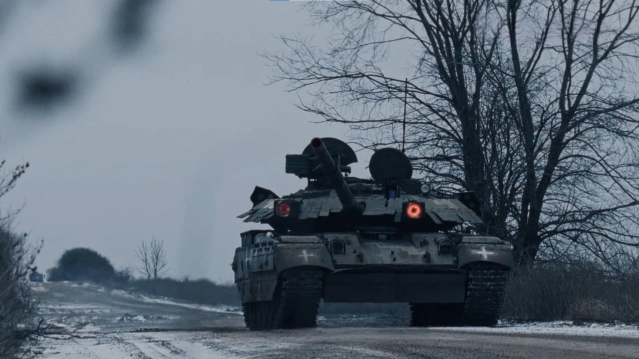
The main battle tank BM OPLOT is a tracked combat vehicle with high firepower, reliable protection and high mobility.
The Ukrainian main battle tank BM OPLOT is a tracked combat vehicle with high firepower, reliable protection and high mobility.
The tank is designed to engage with fire all types of ground (surface) and low-flying air targets at low speeds in conditions of enemy fire resistance.
The tank was developed by KMDB named after. Morozov based on the T-80UD, a series of Soviet T-80 tanks. The chief designer of the vehicle is Doctor of Technical Sciences, Professor, Lieutenant General M.D. Borisyuk, General Designer for the creation of armored vehicles and artillery systems, Head of the KMDB KP. Produced by the ZTM plant named after. Malysheva.
At the moment, the tank is in service with Ukraine and Thailand, and is also located at the training center of the US Armed Forces.
Armament


| Parameter | Value |
|---|---|
| Tank gun | |
| Brand | KBA-3 |
| Caliber, mm | 125 |
| Shutter type | Horizontal wedge, semi-automatic |
| Vertical pumping angles (to hard stops), degrees | from -4 to +15 |
| Horizontal guidance angle (together with the tank turret), degrees | 360 |
| Dispersion: | |
| Horizontally | 0.2t.d.(BPS, KS D=2000m) |
| Vertical | 0.2t.d.(BPS, KS D=2000m) |
| Coaxial machine gun | |
| Mark | KT-7.62 (PKT) with removal of powder gases |
| Caliber, mm | 7.62 |
| Technical rate of fire, rds/min. | 700…800 |
| Anti-aircraft machine gun installation | |
| Type | autonomous |
| Control | remote |
| Control mode | automatic, vertically stabilized |
| Armament, brand | KT-12.7 |
| Caliber, mm | 12.7 |
| Power | tape |
| Technical rate of fire, rds/min. | 700 |
| Number of cartridges in the belt, pcs. | 150 |
| Maximum firing range, m: | |
| Air targets | 2000 |
| For ground targets | 2000 |
| Angles of fire (targeting), degrees: | |
| Vertical | from -3 to 60 |
| Horizontal | 360 |
Loading mechanism


The loading mechanism is a complex designed for automatic loading of a gun with any type of shot and consisting of a conveyor, an automatic loader and a control system.
| Parameter | Value |
|---|---|
| Number of projectile types | electrohydromechanical with constant loading angle |
| Conveyor capacity, lines | 28 |
| Rotation of the conveyor | two-way |
| Conveyor rotation speed, degrees/s | 25…33 |
| Duration of loading one shot, s: | |
| Minimum | 7 (when turning the conveyor by 1 step) |
| Maximum | 12.5 (when the conveyor is rotated 180°) |
| Loading time for firing shots from manual drives MZ, min., no more: | |
| When turning the conveyor by 1 step | 1.0 |
| When turning the conveyor by 14 steps | 1.6 |
| Removing the spent pallet | catching and placing in an empty tray without depressurizing the fighting compartment |
| Method of chambering a shot | tandem chambering (projectile-charge) in one cycle |
| Availability of redundant drives | manual: conveyor drive, manual feed mechanism, conveyor stopper and gun stopper |
| Time to load the conveyor with shots (in loading mode), min. | 15…20 |
The tank loading mechanism control system is designed for:
- ensuring control of the operation of mechanical and hydraulic units of the MZ
- ensuring control of firing circuits from a cannon and coaxial machine gun
- storing information about the types of shots loaded into the MZ conveyor
Fire control complex


KUO provides:
- automatic development and testing of weapon aiming angles and lateral lead, taking into account various deviations of firing conditions from normal
- duplicate shooting from the commander’s position from a cannon and coaxial machine gun
- firing from the commander’s seat from an anti-aircraft machine gun
| Parameter | Value |
|---|---|
| Ready time for work, min., no more than | 3.0 |
| Preparation time for the first shot from a cannon, s | |
| from place | 10…12 |
| on the move | 10…15 |
| Daygunner’s sight 1G46-M | |
| Type | optical sight with two-plane independent stabilization of the field of view, with a laser rangefinder and a laser missile control channel |
| Magnification, times | 2.7…12 |
| Field of view, degrees | 4…20 |
| Pointing angles of the stabilized line of sight, degrees: | |
| in the vertical plane | -15…+20 |
| in the horizontal plane | ±(8±1) |
| together with the tower | 360 |
| Sighting speed, degrees/s: | |
| In the vertical plane: | |
| minimum, no more than | 0.05 |
| smooth guidance | from 0.05 to 1.0 |
| maximum, not less than | 3.0 |
| In the horizontal plane: | |
| minimum, no more than | 0.05 |
| smooth guidance | from 0.05 to 1.0 |
| maximum, not less than | 3.0 |
| Laser rangefinder | |
| range of measured range, m | 400…5000 |
| measurement error, m | ±10 |
Thermal imaging complex


1 - head mirror block; 2 - indication of sight activation; 3 - forehead lock lever; 4 - key space for rough alignment vertically; 5 - micromonitor eyepiece; 6 - micromonitor diopter adjustment handle; 7 - STOP-DISTANCE handle of the drive; 8 - control panel; 9 - adjusting the image contrast in the micromonitor; 10 - toggle switch for turning on the heating of the eyepiece; 11 - adjusting the brightness of the image in the micromonitor; 12 - indicator for turning on the heating of the micromonitor ocular lens; 13 - adjustment of OUT.GN of the interface block; 14 - adjustment of Kr GN of the interface block; 15 - micromonitor headband; 16 - forehead lock button; 17 - desiccant cartridge.
Designed for observation, detection, recognition and identification of targets and ensuring aimed shooting from a cannon and a coaxial machine gun, in all operating conditions.
| Parameter | Value |
|---|---|
| Brand | PTT-2 |
| Type | thermal imaging, monocular (with built-in micromonitor) |
| Spectrum of working wavelengths, microns | from 8 to 12 |
| Wide field of view, °, not less than: | |
| vertical | 6.75 |
| horizontally | 9 |
| Narrow field of view, °, no less: | |
| vertical | 2.25 |
| horizontal | 3 |
| Field of view with electronic magnification, °, not less than: | |
| vertical | 1.12 |
| horizontal | 1.5 |
| electronic magnification | 1.5x1.12 |
| Target detection range with a thermal contrast of the object relative to the background of at least 5 C, in a narrow field of view m, at least: | 8000 |
| Target recognition range with a thermal contrast of the object relative to the background of at least 2 C, in a narrow field of view m, at least: | 4500 |
| Target identification range, m, not less than: | |
| Target identification range with a thermal contrast of the object relative to the background of at least 2 C, in a narrow field of view m, at least: | 2500 |
| Ready time (depending on ambient temperature), min | from 5 to 8 |
| Visual field stabilization: | |
| vertical | electric drive |
| horizontally | together with the tower |
| Pumping range, ° | from -15 to +20 |
Panoramic sighting system

1 – TKN-6 sight; 2 – electrical unit EB-6; 3 – control unit for the BUG-6 head; 4 – switching unit BK-6; 5 – parallelogram drive, 6 – gun position sensor, 7 – guidance panel, 8 – TPV camera control panel.
The complex is intended for:
- detection, recognition and identification of ground and air targets in day and night conditions from the tank commander’s seat
- measuring the range to the target with a laser rangefinder
- issuing target designation to the gunner
- firing from a cannon and a coaxial machine gun from the commander’s seat in the backup weapons control mode
- firing from an anti-aircraft machine gun.
| Parameter | Value |
|---|---|
| Visual field stabilization | independent, in two planes |
| Pointing angles of the stabilized line of sight, degrees: | |
| down, no less than | 15 |
| up, no less than | 60 |
| in the horizontal plane | 360 |
| Magnification factor of the daytime visual channel, times | 1.2 6.0 12.0 |
| Field of view of the daytime visual channel, deg. | 30 10 5.5 |
| Field of view of the thermal imaging channel, degrees: | |
| wide field of view | 9x6.75 |
| narrow field of view | 3x2.25 |
| electronic magnification | 1.5x1.12 |
| Spectral range of thermal imaging camera, microns | 8-12 |
| Detection range of a “tank” type target, m, not less than: | |
| via visual channel | 5500 |
| through a thermal imaging channel in a narrow field of view | 8000 |
| Range for measuring distance to target, m | 200-9500 |
| Root mean square error of measuring the range to a target with a laser rangefinder, m, no more than | ±5 |

Main weapon stabilizer
The main weapon stabilizer provides stabilization and stabilized weapon guidance in the vertical and horizontal planes.
| Parameter | Value |
|---|---|
| Type | 2E42M |
| Vertical guidance drive | electrohydraulic |
| Horizontal guidance drive | electromechanical |
| Average stabilization error, mrad: | |
| in the vertical plane | 0.3 |
| in the horizontal plane | 0.4 |
| Hover speedI guns, deg./s: | |
| in the vertical plane: | |
| minimum, no more than | 0.05 |
| target | 0.05…1 |
| transfer | 4…6 |
| in the horizontal plane: | |
| minimum, no more than | 0.05 |
| target | 0.05…1 |
| transfer | 35…40 |
Tank ballistic computer
Type - analog-digital with a system of built-in control and digital interrogation of parameters, automatic generation of aiming and lead angles for all types of projectiles and a coaxial machine gun, taking into account all topometeoballistic parameters that affect the accuracy of fire, automatic registration and storage of the CDU parameters in various operating modes is ensured.
Parameters automatically taken into account by the computer - range to the target, the tank’s own movement, target speed, side wind speed, roll of the gun trunnion axis, angular speed of the target in the vertical and horizontal planes, target elevation angle, heading angle of the tank, portable and relative speeds of the tank, initial projectile launch speed.
SUZU anti-aircraft gun control system - designed for:
- ensuring stabilization and stabilized guidance of anti-aircraft installations in horizontal and vertical planes
- automatic generation and input of aiming angles and lateral lead, taking into account deviations of shooting conditions from normal
| Parameter name | Value |
|---|---|
| Roll sensor | |
| Range of measured roll angles of the trunnion axis, degrees, not less than | ±15 |
| Measurement error, degrees, no more than | 0.5 |
| Wind sensor | |
| Type | capacitive |
| Brand | TWO-BS |
| Measurement range of the transverse component of wind speed, m/s, no more than | 20 |
| Measurement error, m/s | ±1 |
| Tank speed sensor | |
| Tank speed measurement range, km/h, not less than | 75 |
| Measurement error, km/h, no more than | 0.5 |
| Tower position sensor | |
| Measurement range of the angular position of the tank turret, degrees, not less than | 360 |
| Measurement error, degrees, no more than | 1 |
| System for accounting for trunk bending SUIT | |
| Range of measured bending angles in vertical and horizontal planes, mrad., not less than | ±5 |
| Measurement resolution, mrad., no more than | 0.1 |


Ballistic protection


Main armor passive protection
Type - anti-ballistic, combined and shielded, using a complex of built-in anti-tandem dynamic protection.
Built-in anti-tandem dynamic protection (VPTDZ Duplet-2M)
The Duplet-2M VPTDZ set is designed to increase the level of tank protection against armor-piercing and cumulative ammunition, including those with tandem warheads.
The VPTDS consists of a nose module and side screens installed on the tank hull, as well as modular sections located along the outer perimeter of the frontal and side sections of the turret and containers installed on the roof of the turret.

Mine protection
Ensures the preservation of the combat capability of the crew and the operability of the internal equipment of the tank in the event of an explosion under the track.
Special protective equipment
Optoelectronic countermeasures complex

To increase the tank’s security, it uses an optical-electronic countermeasures complex.
The optical-electronic countermeasures complex provides:
- suppression of ATGM control systems with feedback via the IR coordinator due to light interference in the ±2° sector in the vertical plane
- disruption of targeting of ATGM tanks using laser target illumination and heads with semi-active laser homing, as well as artillery systems with laser rangefinders, due to remote placement of aerosol curtains in the sector ±45° relative to the bore of the main weapon
- suppression of ATGM control systems with feedback via the IR coordinator due to the installation of light interference in a sector of ±20° relative to the bore of the main weapon in the horizontal plane and ±2° in the vertical plane.
| Parameter | Value |
|---|---|
| Optical-electronic suppression station | |
| Ready time, s | 60 |
| Continuous operation time, h | 6 (unlimited in combat conditions) |
| Sector of light interference, degrees: | |
| In the vertical plane | ±2 |
| In the horizontal plane relative to the gun axis | ±20 |
| Aerosol curtain installation system | |
| Operating mode | automatic, semi-automatic, manual |
| Response time of the complex in automatic mode, s, less than | 0.5 |
| Viewing sector by four laser radiation indicators, degrees: | |
| horizontally | 360 |
| vertical | -5…+25 |
| Number of mortars, pcs. | 12 |
| Grenade caliber, mm | 80 |
| Distance of the curtain, m, not less than | 50 |
| Grenade used: | |
| Time of formation of the curtain, s, no more than | 3 |
| Average dimensions of the curtain created by one grenade, m | 10x15 |
| Lifetime of the effective curtain, s | 60 |
###Collective defense system
The collective protection system provides protection for the crew and internal equipment from the damaging factors of a nuclear explosion, radioactive, toxic substances and bacterial agents, as well as detection and suppression of fires in the habitable and engine compartments.
Defense system against weapons of mass destruction
Radiation and chemical reconnaissance device PRHR-M1
The PRHR-M1 device is designed for continuous monitoring, detection, signaling and control of actuators of protective equipment:
- with powerful gamma radiation (nuclear explosion)
- with gamma radiation from a radioactively contaminated area with measurement of the exposure dose rate of gamma radiation
- when vapors of toxic substances of a potential enemy appear in the air
When toxic substances appear in the ambient air or the presence of gamma radiation from the area, the device provides a light and sound alarm, as well as a command that turns on the supercharger and moves the air filter valve to the filter ventilation position.
When detecting powerful gamma radiation, the device providesat the light and sound alarm, as well as the command that stops the engine, switches the FVU valve to filter ventilation mode, stops the supercharger if it was turned on, and then turns it on after 30…50 s.
The device provides testing of its electrical circuits without issuing or issuing commands to the actuators.
| Parameter | Value |
|---|---|
| Range of measured gamma radiation exposure dose rate, R/h | 0.2…150 |
| Operation time, s, no more than: | |
| with powerful gamma radiation | 0.1 |
| with gamma radiation from a radioactively contaminated area | 10 |
| when vapors of toxic chemicals appear in the air outside the facility | 40 |
Filter ventilation unit (FVU)
The FVU is designed to clean the outside air from toxic substances, radioactive dust, biological aerosols, supply purified air to the habitable compartment and create excess pressure in it, and ventilate the habitable compartment from fire extinguishing agents after extinguishing a fire.
| Parameter | Value |
|---|---|
| Air consumption, m3/h: | |
| through filter-absorber FPT 100 | not less than 100 |
| bypassing the absorber filter | not less than 390 |
The filter ventilation unit has 2 operating modes:
- ventilation mode, in which the blower supplies dust-free air to the habitable compartment, bypassing the absorber filter
- filter ventilation mode, in which the supercharger supplies purified air to the habitable compartment through an absorber filter.
Fire and explosion suppression system
The system with optical sensors and temperature sensors is designed to detect fires in the habitable and engine compartments and quickly eliminate them; issuing commands to turn on ventilation to remove pyrolysis products from the habitable compartment.
| Parameter | Value |
|---|---|
| Methods of actuation: | |
| automatically | when the on-board network of the product is turned on |
| manually | from the “PO”, “ZO” buttons on the remote control to the corresponding compartments |
| Performance: | |
| by habitable compartment, ms, no more than | 150 |
| by logistics, s, no more than | 10 |
| Multiplicity of action | 2 |
| Number of cylinders with fire extinguishing agent, pcs. | 4 |
Extinguishing is ensured by filling the free space of the compartment where the fire occurred with fire extinguishing agent from cylinders.
The product uses cylinders with a capacity of 2 liters, filled with fire extinguishing agent Freon 114B2 or another composition, as agreed, under a pressure of 75 kgf/cm2. The cylinders are equipped with quick-acting heads with pressure indicators.
To ensure the survivability of the product, two cylinders are installed in the PPO system for each compartment (PO, MTO).
Detection Protection
Distorting coloring
Deforming coloring is intended to reduce the optical visibility of an object against a natural background, distort its image in order to make recognition (identification) difficult, reduce the detection range by reconnaissance means and make it difficult for the gunner to aim at a selected point in its silhouette.
The deforming coloring used is three-color. The primary color is green-protective, the secondary color is gray-yellow and the secondary color is black. Desert coloring option is possible. Four-color pixel warp coloring is also used. The main color is protective green, additional colors are gray-yellow, dark brown and black.
Thermal protection
Thermal protection is designed to reduce the range and probability of detection of a tank by thermal reconnaissance means and homing heads of precision-guided ammunition.
Thermal protection consists of thermal insulating screens.
Thermal smoke equipment
Thermal smoke equipment is designed for setting up smoke screens using diesel fuel.
| Parameter | Value |
|---|---|
| Mode of action | repeated |
| Duration of continuous action, min., no more than | 10 |
| Fuel consumption, l/min. | 10-12 |
Set of camouflage coatings
A set of camouflage coatings (nets) is designed to reduce:
- visibility of the tank in the visible range
- the value of the effective scattering surface of the tank in order to reduce its detection range using reconnaissance and weapon guidance radar stations
- thermal radiation from the heated outer surfaces of the tank in order to reduce its detection range using thermal imaging devices and reduce the likelihood of the tank being “captured” by IR homing heads of anti-tank weapons (ATGMs, mortar mines, artillery shells)
| Parameter | Value |
|---|---|
| Level of reduction in power of the reflected signal from a camouflaged object (in the range of 0.8-4 cm), dB, no more than | 18 |
| Reducing the probability of detecting a tank under a mask by airborne radar reconnaissance equipment, at ranges of 20 km or more (with a terrain resolution of 5…15 m), compared with an open one, by at least | 2 |
| Reducing the likelihood of a tank being captured under a mask by radar weapon guidance systems, compared to an open one, by at least | 2 |
| Probability of detecting a camouflaged object on an aerial photograph, with resolutionon the ground not lower than 0.2 m, should not exceed | 0.3 |
| During visual observation, the object under the mask should not be recognized at ranges, m, not less than | 1000 |
| Reduction in the level of IR radiation of an object under a mask compared to an open one, times, not less than | 1.5 |
| Applicable paint colors | protective green, gray-yellow |
Powerplant
The power plant is a complex of components and assemblies, including the engine and its servicing systems: fuel supply, air supply, lubrication, cooling, exhaust gases and heating. The power plant can be operated in the ambient temperature range from -40°C to +55°C.
Engine


The 6TD engine is a multi-fuel six-cylinder two-stroke liquid-cooled diesel engine.
| Parameter | Value |
|---|---|
| Maximum diesel stand power when operating on diesel fuel, kW (hp) | 882 (1200) |
| Maximum torque of a diesel engine when operating on diesel fuel at a diesel engine speed of HF (2050±10) min.-1, Nm (kgf.m) | 3135 (320) |
| Crankshaft rotation speed at maximum power, min.-1 | 2600 |
| Specific fuel consumption in maximum power mode, g/kW.h (G/hp.h) | 211…231 (155…170) |
| Dry diesel mass, kg | 1180 |
| Overall dimensions of diesel engine, mm: | |
| length | 1602 |
| width | 955 |
| height | 581 |
The engine is adapted to an automated transmission control system, the regulator is equipped with a fuel pump rack travel sensor, and the diesel engine is equipped with a crankshaft speed meter.
The electrohydromechanical speed controller implements a special mechanism that limits the fuel supply in the frequency range 800…2000 min.-1, which ensures a decrease in the optical density of the exhaust gases in start-up and free acceleration modes.
The engine fuel equipment uses injectors with a shut-off needle.
The engine consists of a block, crank mechanism, crankcases, cylinders, gear mechanism, compressor, gas turbine and attached units: starter-generator, water pump, TK-150 air compressor, fuel pump regulator, fuel filters, high-pressure fuel pumps, oil centrifugal filter, air distributor and other components.
The engine cylinders are located horizontally. Each cylinder has purge and exhaust ports. Purge windows serve to purge and fill the cylinders with air, exhaust windows ensure the removal of exhaust gases from the cylinders. The improved configuration of the purge ports provides improved efficiency by improving the gas exchange and mixture formation process. The exhaust gases leaving the cylinders enter the gas turbine through the exhaust manifold.
Each cylinder has two opposing moving pistons. When they come together as close as possible, a combustion chamber is formed. Each piston is connected to its own crankshaft through a connecting rod. During reciprocating motion, the pistons open and close the purge and exhaust windows, i.e. perform the functions of a gas distribution mechanism. The pistons use an improved needle bearing for the upper end of the connecting rod, which provides the ability to increase the maximum combustion pressure, service life and reliability.
The charge air compressor improves diesel parameters due to a more efficient compression process achieved by improving the aerodynamics of the flow section.
A gas turbine converts exhaust gas energy into mechanical energy, which is used to drive a compressor.
The engine is installed in the engine-transmission compartment. Its installation does not require alignment or adjustment. The axes of the engine crankshafts are located transverse to the longitudinal axis of the tank.
The engine has three mounting points: two yokes at the rear and a pivot mount at the front.
Fuel supply system
The fuel supply system includes:
- fuel tanks
- drainage tank
- fuel distribution valve
- shut-off valve for external tanks
- fuel priming pumps
- filling fuel filter, coarse filter
- fine filter
- petrol centrifugal pump
- filling pump with tap
- air separating tank, check valve
- fuel meters
- pipelines
The fuel for powering the engine is placed in tanks with a total capacity of 1140 liters.
Fuel used: diesel fuel, jet fuel, gasoline and mixtures thereof.
The system supplies the engine with fuel both from each group of tanks separately, and from both groups of tanks simultaneously.
The fuel system also provides power to the power unit located on the right fender using pipelines led through the side.
Refueling can be done centrally through the tank filler necks, as well as using a refueling pump.
| Parameter | Value |
|---|---|
| Capacity ininternal fuel tanks, l | 575 |
| Capacity of external fuel tanks, l | 570 |
| Capacity of additional fuel barrels, l | 380 (190x2) |
Air supply system
The engine air supply system is designed to clean the air entering the engine from dust. Three-stage air purification with ejection dust removal. The first stage is a hopper with an inertial grille, the second and third stages are a two-stage cassette air cleaner.
The system consists of an air cleaner with a dust removal ejector, an air intake hopper with an inertial grille and a dust removal ejector from an inertial grille.
The air cleaner is two-stage. The first stage provides preliminary air purification from dust by 99.78%. After passing the second stage, the air is purified to 99.98%. The cassettes make up the second stage of the air purifier.
Engine lubrication system
The engine lubrication system is designed to place oil in the tank, supply it to the engine, clean and cool the oil used in the engine.
The engine lubrication system consists of an internal oil tank with an intake filter, an oil cooler, an oil injection pump, an engine charge pump, two scavenge pumps, an oil centrifugal filter, an oil gauge and pipelines.
The lubrication system is circulation, based on the dry sump principle.
An oil tank with a capacity of 105 liters is installed in the front part of the power compartment between the bulkhead and the engine. Oil is taken to power the engine from the middle compartment, which is replenished with oil from other compartments.
The system is equipped with a minimum oil pressure indicator.
Cooling system
| Parameter | Value |
|---|---|
| Cooling system | liquid, high-temperature, closed type with forced circulation of coolant and ejection cooling of radiators, designed to ensure thermal operating conditions of the engine |
| Pumping coolant through a diesel engine at an engine speed of 2600 min.-1, not less, m3/hour | 38 |
| Filling capacity of the system, l | 94 |
The cooling system includes:
- ejector, engine water pump
- radiators
- compensation tank
- steam-air valve
- heater with air heater
- engine cavities
- cooling belts for flue connector
- engine water drain valve
- valve for draining water from the heater and pipelines
Water radiators provide heat removal from the coolant and are installed in the ejector box of the roof of the engine compartment.
The system is equipped with a minimum coolant level sensor and a maximum coolant temperature sensor.
The efficiency of the cooling system is regulated by the amount of gases passing through the ejector.
Exhaust system
The system ensures the passage of cooling atmospheric air through the radiators by using the energy of the engine exhaust gases and releasing the exhaust gases.
The system consists of a compensator, a gas duct, an adapter welded into the right side of the roof of the engine-transmission compartment together with a bypass gas duct, a receiver with a nozzle apparatus, an ejector flow section and output shutters.
To cool the joint, there are water jackets in the flue through which the coolant of the cooling system circulates.
Heating and heating system
The heating system is an integral part of the cooling system and serves to warm up the engine and oil before starting, and to maintain the engine in a state of readiness for starting in cold weather.
The engine is heated by the coolant heated by the heater, and the oil in the engine oil tank is heated by the exhaust gases of the heater.
The heating system includes a heater, a flame pipe of the engine oil tank and pipelines.
The heater is designed to heat the coolant and ensure its circulation through the cooling system lines when the engine warms up, and to heat the oil with exhaust gases in the engine oil tank.
Engine starting system
| Parameter | Value |
|---|---|
| Start methods: | |
| main | electric starter from four batteries |
| auxiliary | compressed air from cylinders |
| combined | electric starter from the battery, high pressure generator and compressed air at the same time |
| from an external source | using electricity or compressed air from a similar machine |
| from a tug | used in case of impossibility of starting the engine using the above methods |
| Starting aids | * heater * electric torch heating * oil injection |
| Start temperature of a cold diesel engine without the use of preheating means: | |
| on oil AZMOL Garant, GALOL M-4042, M16IHP-3 | up to 5 °C |
| on low-viscosity oil M8B2S | up to minus 25 °C |
Reversible transmission
The reversible transmission is designed to increase the speed of the tank when moving forward and in reverse. Increased (accelerated) reverse gears provide, if necessary, a quick change of positions in combat conditions without rturning the tank. The transmission is adapted to the automated control system and is equipped with a rotation speed sensor.
The reversible transmission consists of a gearbox (Gearbox) and is connected coaxially to the reversible final drive. Based on their location in the tank, transmissions are classified as right-handed or left-handed. They are located on the right and left sides of the hull coaxially with the engine output shaft.
Gearboxes
Planetary type gearboxes with friction gearing. Gearboxes provide 7 forward and 1 reverse gears.
Reversible final drives
Reversible final drives consist of two planetary gears. Forward and reverse are activated by a gear clutch, which provides an additional four reverse gears.
Gear speeds (km/h)

Performance characteristics of the main battle tank BM OPLOT
| Parameter | Unit of measurement | Value |
|---|---|---|
| General information | ||
| Type | main battle tank | |
| Total weight | t | 51 |
| Crew | persons | 3 |
| Specific power | kW (hp/t) not less than | 18.2(24.7) |
| Specific pressure on soil | MPa (kgf/cm2) no more than | 0.097 (0.97) |
| Operating temperature | °C | -40…+55 |
| Main dimensions | ||
| Length | ||
| with the gun forward | mm | 9720 |
| with cannon back | mm | 9750 |
| body | mm | 7075 |
| Tank width | ||
| by caterpillar | mm | 3400 |
| by removable protective screens | mm | 4215 |
| Height according to the commander’s sight | mm | 2800 |
| Length of the supporting surface | mm | 4290 |
| Ground clearance | mm | 470…500 |
| Tread width | mm | 2800 |
| Operational data (for a single tank in various road conditions) | ||
| Movement speed | ||
| Average on dry dirt road | km/h | 40…45 |
| Maximum on paved roads | km/h | 70 |
| In reverse gear: | ||
| minimum | km/h | 4.8 |
| maximum | km/h | 31.3 |
| Fuel consumption per 100 km | ||
| On a dry dirt road | l, up to | 325…370 |
| On paved roads | l, up to | 300 |
| Oil consumption per 100 km | ||
| On a dry dirt road | l, up to | 7…19 |
| On a paved road | l, up to | 4…11 |
| Fuel range | ||
| On a dry dirt road | ||
| on main fuel tanks | km | 350 |
| with additional barrels | km | 450 |
| On a paved road | ||
| on the main fuel tanks | km | 400 |
| with additional barrels | km | 500 |
| Overcome obstacles | ||
| Maximum angle of elevation | degrees | 32 |
| Maximum roll angle | degrees | 25 |
| Ditch width | m | 2.85 |
| Height of vertical wall | m | 1.0 |
| Ford depth (without preliminary preparation) | m | 1.8 |
| Water obstacles using underwater driving equipment | ||
| Depth | m | 5.0 |
| Width | m | no limit |
| Ammunition | ||
| Shots to the cannon | pcs. | 46 |
| (of which in the loading mechanism conveyor) | pcs | 28 |
| Type of gun ammunition | pieces | OFS, BPS, KS, UR |
| Cartridges: | ||
| to the KT-7.62 machine gun | piece | 1250 (250x5) |
| to the KT-12.7 machine gun | pcs | 450 (150x3) |
| to the AKS machine | pcs. | 450 |
| to the signal gun | pcs | 12 |
| F-1 hand grenades | pcs. | 10 |
| Aerosol grenades | pcs. | 12 |
Photo:


Video:
Spoiler
https://www.youtube.com/watch?v=cNyprt01B2E&t=25s&ab_channel=Andrei
https://www.youtube.com/watch?v=GnJkb4LYcjg&ab_channel=Andrei
https://www.youtube.com/watch?v=2mcgXHFRCEA&ab_channel=Andrei
https://www.youtube.com/watch?v=0jh830svq78&ab_channel=Andrei
https://www.youtube.com/watch?v=XR3fUuNRZKQ&ab_channel=Andrei
https://www.youtube.com/watch?v=wWuqxouYIH4&ab_channel=Andrei
https://www.youtube.com/watch?v=erg4sA-t7Qs&ab_channel=Andrei
https://www.youtube.com/watch?v=yRMlm9jCMho&ab_channel=Andrei
https://www.youtube.com/watch?v=Z9Zkz99KW3Q&pp=ygUIQk0gT3Bsb3Q%3D
https://www.youtube.com/watch?v=-K2V73DyC_0&pp=ygUIQk0gT3Bsb3Q%3D
https://www.youtube.com/watch?v=q58LMmnJpn0&pp=ygUIQk0gT3Bsb3Q%3D
https://www.youtube.com/watch?v=mKoqfTj6UlI&pp=ygUIQk0gT3Bsb3Q%3D
Mod for WT Live: WT Live // Model by DanPogan